
Position-free sensor brushless DC motor rotor position compensation method

A technology of brush DC motor and rotor position, which is applied in the direction of electronically commutated motor control, electrical components, electronic commutator, etc., which can solve the unavoidable, large rotor position detection error, and the inability to guarantee the phase compensation accuracy in the full speed regulation range, etc. problems, to achieve the effects of easy realization, improved efficiency, and favorable engineering application

Active Publication Date: 2015-08-12
NORTHWESTERN POLYTECHNICAL UNIV
View PDF5 Cites 4 Cited by
  • Summary
  • Abstract
  • Description
  • Claims
  • Application Information

AI Technical Summary

Problems solved by technology

On the one hand, the terminal voltage method is the most mature and commonly used sensorless brushless DC motor rotor position detection method, but due to the influence of load size, filter circuit delay and other factors, the rotor position detection error is large and unavoidable
On the other hand, the commonly used rotor position compensation method is the fixed value compensation method, which cannot guarantee the accuracy of phase compensation in the full speed range, and has certain limitations.

Method used


Image

  • Position-free sensor brushless DC motor rotor position compensation method
  • Position-free sensor brushless DC motor rotor position compensation method
  • Position-free sensor brushless DC motor rotor position compensation method

Examples


Embodiment Construction

[0042] Now in conjunction with embodiment, accompanying drawing, the present invention will be further described:

[0043] A sensorless brushless DC motor control system for a 260W fuel pump is tested and verified, and the rated operating voltage of the motor is 28V.

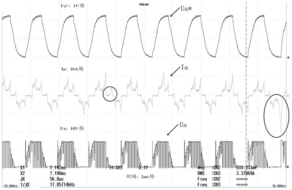
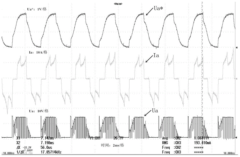
[0044] Step 1: Under no-load conditions, control the closed-loop operation of the motor at the rated speed, adjust the rotor position compensation angle of the motor, and observe the symmetry of the motor phase current and terminal voltage. Record the compensation angle value θ of the rotor position of the motor when the phase current and terminal voltage waveforms have the best symmetry b1 =3°, and the corresponding bus current value I d1 = 1A.

[0045] Step 2: Under the condition of rated load, control the closed-loop operation of the motor at the rated speed, adjust the rotor position compensation angle of the motor, and observe the symmetry of the phase current and terminal voltage of the motor. Record th...


PUM


Abstract

The invention relates to a position-free sensor brushless DC motor rotor position compensation method. The relation between two major factors (load size and filter delay) affecting the position detection precision of a rotor and a phase delay angle is analyzed, then the relation is processed to form a linear equation in two unknowns by use of a mathematic fitting mode, and finally rotor position compensation is carried out relevantly according to the equation. According to the invention, the phase conversion precision of a motor is improved, the torque ripple is reduced, the motor efficiency is enhanced, and out-of-step faults caused by severe lagging of phases are avoided.

Description

technical field [0001] The invention belongs to the precise commutation control of motors, in particular to a method for compensating the rotor position of a brushless DC motor without a position sensor. Background technique [0002] The brushless DC motor is mainly composed of three parts: the motor body, the electronic commutation circuit and the rotor position sensor. As the component with the highest failure rate of the brushless DC motor, the position sensor reduces the reliability of the brushless DC motor and increases the cost and volume of the motor. Therefore, the brushless DC motor without position sensor and its control technology has become a research hotspot in recent years. Although the control technology of brushless DC motor without position sensor is relatively mature, its commutation control accuracy is generally not as good as that of position sensor control. When the commutation of the brushless DC motor is inaccurate, it will generally cause the torqu...

Claims


Application Information

Patent Timeline
Patent Type & Authority Applications(China)
IPC IPC(8): H02P6/18
CPCH02P6/182Y02P80/10
Inventor 马瑞卿刘青韩伟健
Owner NORTHWESTERN POLYTECHNICAL UNIV
Learn More