
Rotor Concentrated Magnetic Double Stator Transverse Magnetic Field Permanent Magnet Synchronous Motor

A technology of permanent magnet synchronous motor and transverse magnetic field, applied to synchronous motors with stationary armature and rotating magnets, magnetic circuit shape/style/structure, electrical components, etc., which can solve the problem of low space utilization and winding utilization, Low torque density and power density, complex structure and other problems, to achieve the effect of shortening the ineffective length, improving torque density and power density, and wide application prospects

Active Publication Date: 2017-03-29
HARBIN INST OF TECH
View PDF7 Cites 0 Cited by
  • Summary
  • Abstract
  • Description
  • Claims
  • Application Information

AI Technical Summary

Problems solved by technology

[0006] The purpose of the present invention is to solve the problems of traditional transverse structure motors, complex structure, low space utilization rate and winding utilization rate, low torque density and low power density, and provides a rotor magnetic concentration type double stator transverse magnetic field permanent magnet synchronization motor

Method used


Image

  • Rotor Concentrated Magnetic Double Stator Transverse Magnetic Field Permanent Magnet Synchronous Motor
  • Rotor Concentrated Magnetic Double Stator Transverse Magnetic Field Permanent Magnet Synchronous Motor
  • Rotor Concentrated Magnetic Double Stator Transverse Magnetic Field Permanent Magnet Synchronous Motor

Examples


specific Embodiment approach 1

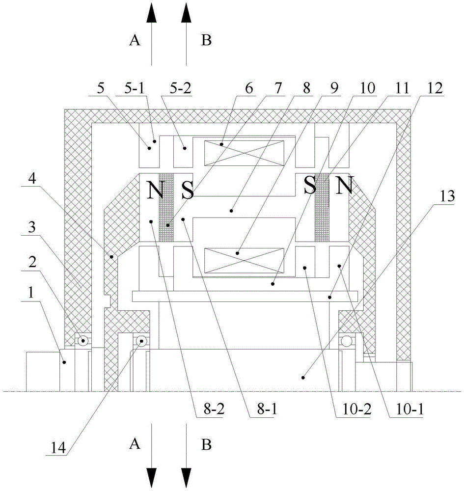
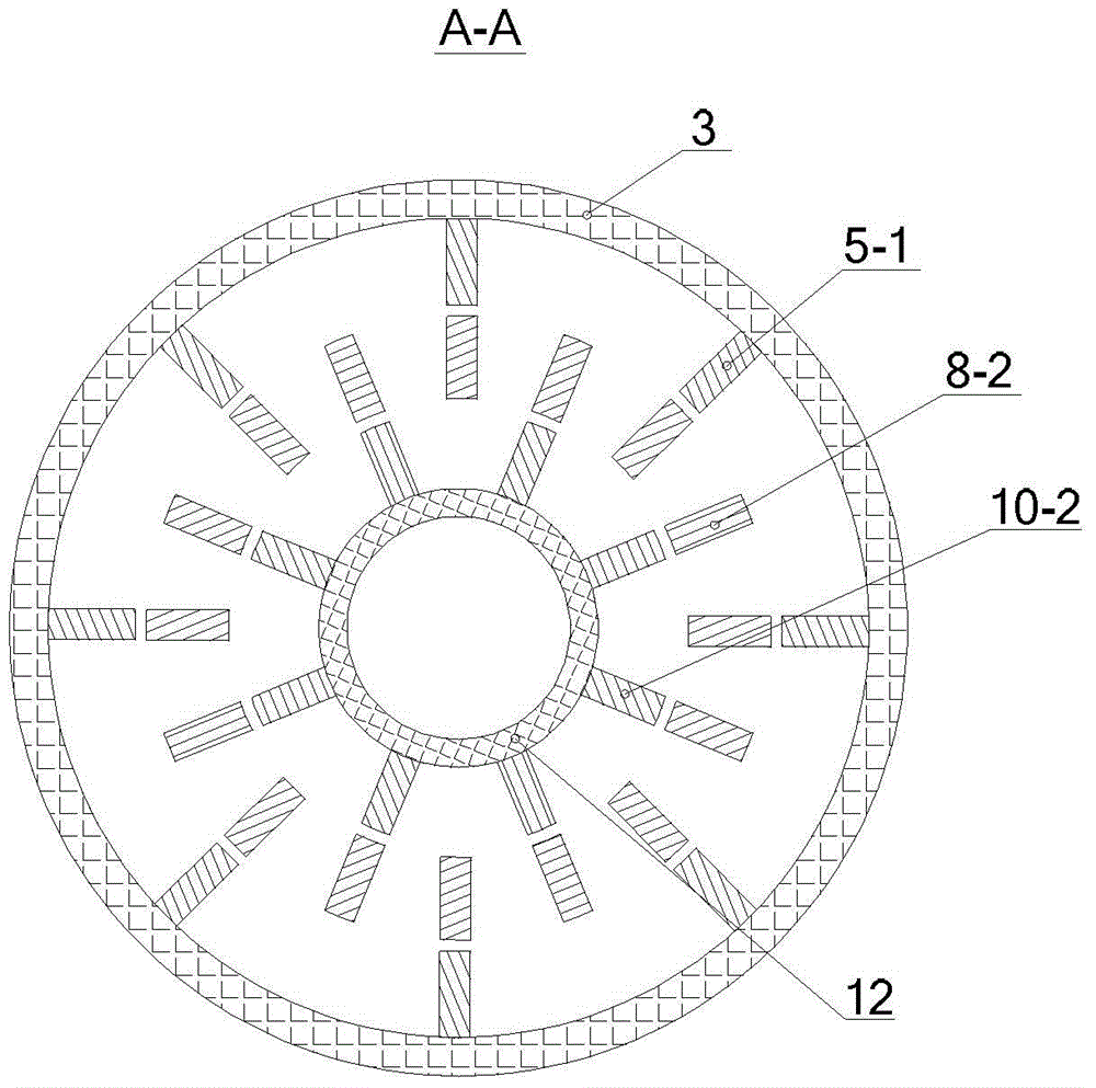
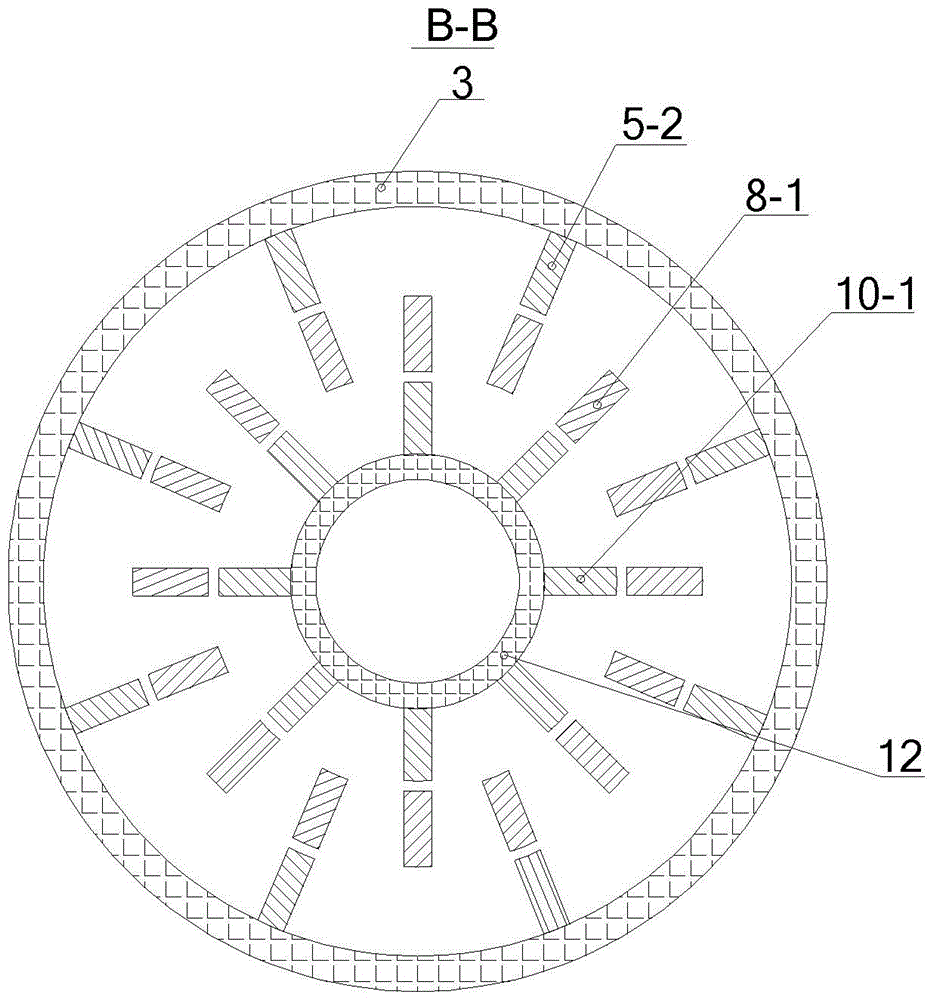
[0022] Specific implementation mode one: the following combination Figure 1 to Figure 5 Describe this embodiment, the rotor magnetic concentration double-stator transverse magnetic field permanent magnet synchronous motor described in this embodiment includes a stator, a rotor, a casing 3 and a rotor support 4, the stator includes an outer stator and an inner stator, and the rotor is located at the outer stator and the inner stator. Between the stators, and fixed on the rotor bracket 4; the first working air gap is formed between the outer stator and the rotor, and the second working air gap is formed between the inner stator and the rotor;

[0023] The outer stator includes an outer stator core 5 and an outer stator armature winding 6, the outer stator core 5 includes p first U-shaped outer stator cores 5-1 and p second U-shaped outer stator cores 5-2, and p first U-shaped outer stator cores 5-1 and p second U-shaped outer stator cores 5-2 are alternately and evenly distribu...

specific Embodiment approach 2

[0040] Specific implementation mode two: the following combination Figure 1 to Figure 5 Describe this embodiment, the rotor magnetic concentration type double-stator transverse magnetic field permanent magnet synchronous motor described in this embodiment includes a three-phase stator, a three-phase rotor, a casing 3 and three rotor supports 4, and each phase stator includes an outer stator and an inner stator The rotor of each phase is located between the outer stator of the phase and the inner stator of the phase, and is fixed on a rotor bracket 4; the first working air gap is formed between the outer stator and the rotor, and the second working air gap is formed between the inner stator and the rotor. Air gap; three-phase stators are arranged side by side along the axial direction;

[0041] The outer stator includes an outer stator core 5 and an outer stator armature winding 6, the outer stator core 5 includes p first U-shaped outer stator cores 5-1 and p second U-shaped o...


PUM


Abstract

The invention relates to a rotor magnetic concentrating double-stator transverse magnetic field permanent magnet synchronous motor, belongs to the field of motors, and aims to solve the problems of complex structure, low space utilization ratio, low winding utilization ratio, low torque density and low power density in a conventional transverse structure motor. The rotor magnetic concentrating double-stator transverse magnetic field permanent magnet synchronous motor comprises stators, a rotor, a shell and a rotor bracket, wherein the stators comprises an outer stator and an inner stator; the rotor is positioned between the outer stator and an inner stator, and is fixed on the rotor bracket; a first working gap is formed between the outer stator and the rotor; a second working gap is formed between the inner stator and the rotor; the outer stator comprises an outer stator iron core and an outer stator armature winding; the outer stator iron core comprises p pairs of U-shaped outer stator iron cores which are staggered bilaterally; the inner stator comprises an inner stator armature winding, an inner stator iron core, a non-magnetic inner stator sleeve and an inner stator shaft; the inner stator iron core comprises p pairs of U-shaped inner stator iron cores which are staggered bilaterally; and the rotor comprises 2p first permanent magnets, 2p second permanents, a rotor iron core and a revolving shaft.

Description

technical field [0001] The invention relates to a permanent magnet motor with high power density and high torque density, belonging to the field of motors. Background technique [0002] Compared with electric excitation motors, permanent magnet motors, especially rare earth permanent magnet motors, have significant advantages such as simple structure, reliable operation, small size, light weight, low loss, and high efficiency; The scope is extremely wide, covering almost every field of aerospace, national defense, industrial and agricultural production and daily life. According to the permanent magnet magnetic circuit structure, the permanent magnet motor rotor structure is divided into surface mount type and magnetic accumulation type. The rotor adopts a magnetic-concentration structure. Compared with the surface-mounted rotor structure, the effective harmonic flux density in the air gap can be greatly improved, which can increase the power density of the motor and improve...

Claims


Application Information

Patent Timeline
Patent Type & Authority Patents(China)
IPC IPC(8): H02K16/04H02K1/27H02K1/16H02K3/28
CPCH02K1/16H02K1/27H02K16/04H02K21/12
Inventor 郑萍朱少洪隋义程路明周承豫
Owner HARBIN INST OF TECH
Learn More