An infrared led bracket
A technology of LED brackets and infrared rays, which is applied in the direction of electrical components, circuits, semiconductor devices, etc., can solve problems such as the inability to realize the controllability of infrared emission angles, and achieve the effects of increasing stability, improving electrical conductivity, and increasing heat dissipation area
- Summary
- Abstract
- Description
- Claims
- Application Information
AI Technical Summary
Problems solved by technology
Method used
Image

Examples
Embodiment 1
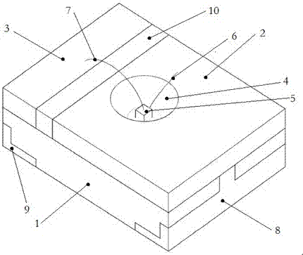
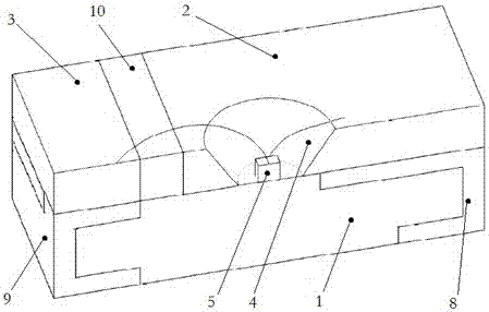
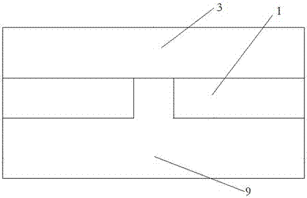
[0027] Such as Figure 1~4 As shown, the novel infrared LED bracket disclosed in this embodiment includes a PCB board 1, on which a first metal bracket 2 and a second metal bracket 3, a first metal bracket 2 and a second metal bracket are arranged An intermediate insulating layer 10 is provided between 3. The first metal bracket 2 is provided with an inverted tapered through hole to form a reflector 4, and an infrared LED chip 5 is fixed on the PCB at the bottom of the reflector. The infrared LED chip passes through the first gold wire 6 and The second gold wire 7 is connected to the first metal bracket 2 and the second metal bracket 3. The two ends of the PCB board 1 are fixedly provided with a first electrode 8 and a second electrode 9 respectively. The first electrode 8 and the second electrode 9 respectively extend to the bottom of the first metal bracket 2 and the second metal bracket 3, and respectively The first metal bracket 2 and the bottom of the second metal bracke...
Embodiment 2
[0036] This embodiment provides a type of infrared LED bracket, such as figure 1 It includes a PCB board 1 on which a first metal bracket 2 and a second metal bracket 3 are arranged, and an intermediate insulating layer 10 is arranged between the first metal bracket 2 and the second metal bracket 3. Preferably, the first metal bracket and the second metal bracket are copper brackets.
[0037] The first metal bracket 2 and the second metal bracket 3 are adhered to the PCB board by conductive adhesive.
[0038] Preferably, in this embodiment, a conductive adhesive can be specially selected, and its raw materials are composed of 65 parts of acrylic glue, 0.06 parts of diphenylmethane diisocyanate, 8 parts of copper powder, 1 part of butyl acetate, and 2 parts of diphenylmethane diisocyanate by weight. Benzoylmethane, 0.7 parts of acetophenone, 0.2 parts of potassium hydroxide, 0.09 parts of zinc sulfate, 6 parts of glycerol. Said acrylic glue is preferably oily acrylic glue, which ca...
Embodiment 3
[0040] This embodiment provides a type infrared LED bracket, the structure of which is the same as the first embodiment. The first metal bracket and the second metal bracket are preferably made of 304 stainless steel.
[0041] Preferably, in this embodiment, a conductive adhesive can be specially selected, and its raw materials are composed of 65 parts of acrylic glue, 0.06 parts of diphenylmethane diisocyanate, 8 parts of copper powder, 1 part of butyl acetate, and 2 parts of diphenylmethane diisocyanate by weight. Benzoylmethane, 0.7 parts of acetophenone, 0.2 parts of potassium hydroxide, 0.09 parts of zinc sulfate, 6 parts of glycerol. Said acrylic glue is preferably oily acrylic glue, which can be realized by commercially available products, particularly preferably the viscosity is 4000-12000 CPS, and the glue is coated to a dry glue thickness of 0.025mm. Adhesion: greater than 2000g / 25mm. Coat the conductive adhesive on the adhesion part, the thickness is 0.2mm, and the st...
PUM
 Abstract
Description
Claims
Application Information
 - R&D
- Intellectual Property
- Life Sciences
- Materials
- Tech Scout
- Unparalleled Data Quality
- Higher Quality Content
- 60% Fewer Hallucinations
Browse by: Latest US Patents, China's latest patents, Technical Efficacy Thesaurus, Application Domain, Technology Topic, Popular Technical Reports.
© 2025 PatSnap. All rights reserved.Legal|Privacy policy|Modern Slavery Act Transparency Statement|Sitemap|About US| Contact US: help@patsnap.com