Ion source electric field structure and ion source device

An ion source and electric field technology, applied in the field of ion sources, can solve the problems of unconcentrated ion beam current distribution, ion beam dispersion, low ion beam effective use efficiency, etc., so as to improve the concentration effect and realize the effect of intelligent adjustment

Pending Publication Date: 2020-09-25
ZHONGSHAN IBD TECH CO LTD +1
View PDF0 Cites 0 Cited by
  • Summary
  • Abstract
  • Description
  • Claims
  • Application Information

AI Technical Summary

Problems solved by technology

[0003] In a commonly used ion source, its electric field structure is mainly realized by the anode part 10, such as figure 1 as shown, figure 1 It is a schematic diagram of the emission angle of a commonly used ion source. The anode part 10 accelerates the ion beam through the action of an electric field. From the figure, it can be found that the ion source itself has a large div

Method used


Image

  • Ion source electric field structure and ion source device
  • Ion source electric field structure and ion source device
  • Ion source electric field structure and ion source device

Examples


Embodiment Construction

[0032] Embodiments of the present application are described in detail below, examples of which are shown in the drawings, wherein the same or similar reference numerals denote the same or similar elements or elements having the same or similar functions throughout. The embodiments described below by referring to the figures are exemplary only for explaining the present application, and are not construed as limiting the present application.

[0033] Those skilled in the art will understand that unless otherwise stated, the singular forms "a", "an", "said" and "the" used herein may also include plural forms. It should be further understood that the wording "comprising" used in the description of the present application refers to the existence of the stated features, integers, steps, and operations, but does not exclude the existence or addition of one or more other features, integers, steps, and operations.

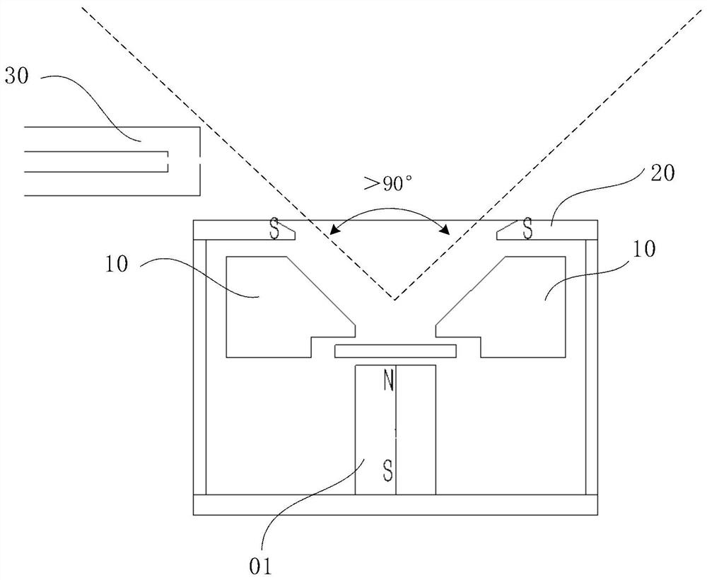
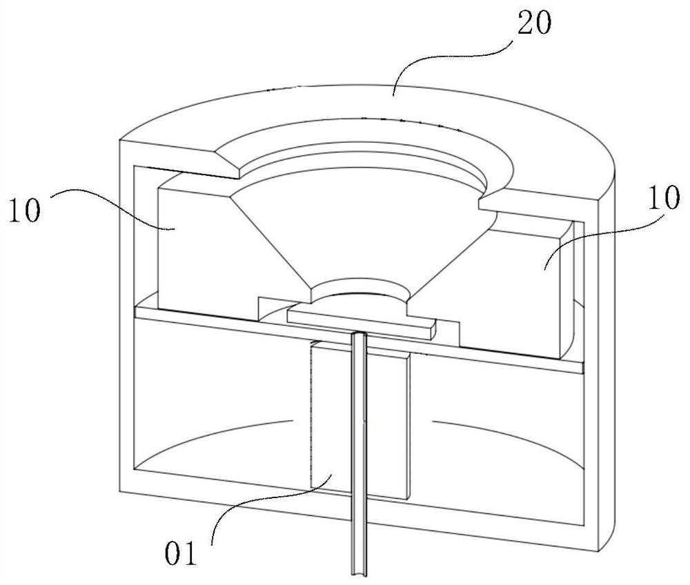
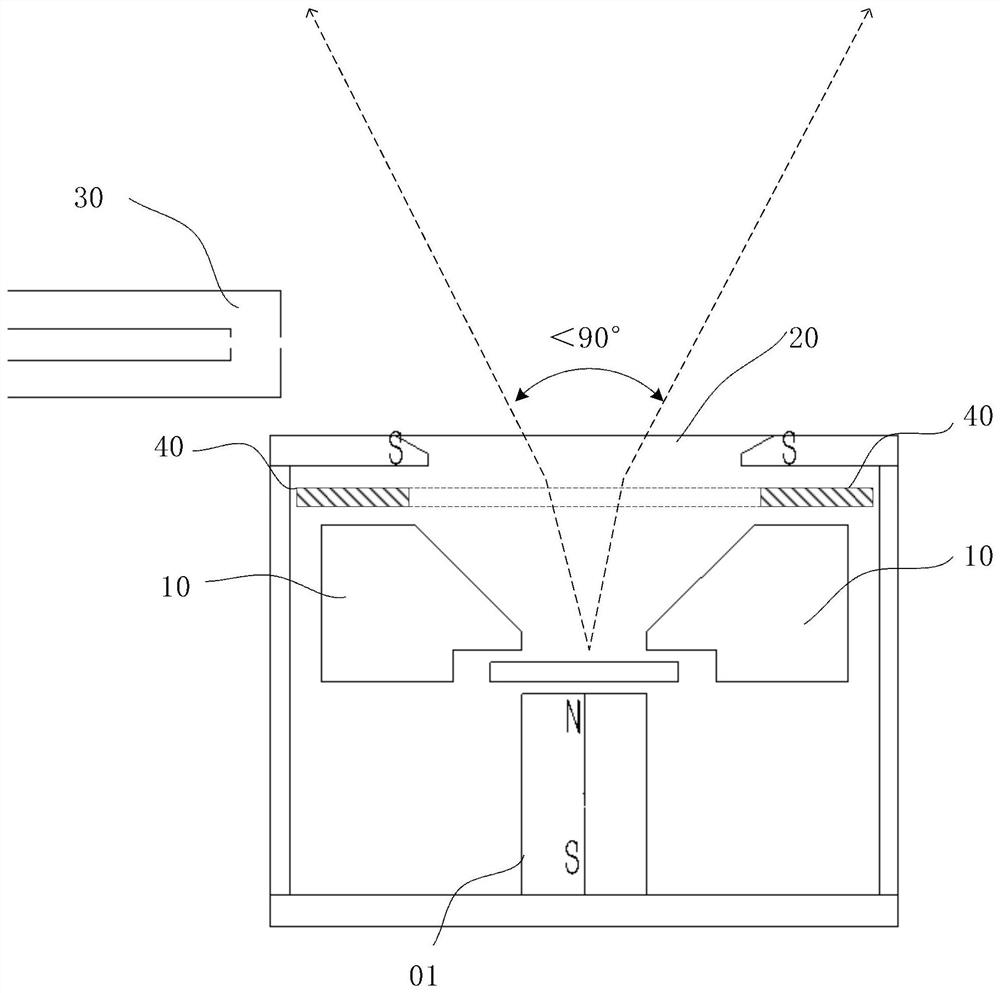
[0034] combine figure 1 shown and figure 2 as shown, figure 2 It ...


PUM


Abstract

The invention relates to an ion source electric field structure and an ion source device. The ion source electric field structure comprises an anode component disposed in a shell, wherein an isolationmetal layer is disposed between the anode component and the shell, the isolation metal layer is of an annular design corresponding to the anode component and is kept in an insulating state with the anode component and the shell, and the isolation metal layer induces an electric field of a voltage through the anode component, and controls the emission angle of an ion beam emitted by the ion sourcethrough the electric field. According to the technical scheme, the annular isolation metal layer corresponding to the anode component is arranged between the anode component and the shell, and the isolation metal layer is located at a suspension potential, induces an electric field of a voltage through the anode component, and controls the emission angle of an ion beam emitted by the ion source through the electric field; and the electric field structure can effectively control the ion beam emission angle range of the ion source, and improve the concentration effect of ion beams emitted by the ion source.

Description

technical field [0001] The present application relates to the field of ion source technology, in particular to an ion source electric field structure and an ion source device. Background technique [0002] Ion source is an applied science and technology with wide application, many types, many sciences involved, strong technological process and very rapid development. As a very commonly used ion source type, the Hall ion source is mostly used in the field of thin film deposition as a deposition auxiliary component to improve the physical properties of thin films. The Hall ion source is that the anode plasmaizes the process gas under the cooperation of a strong axial magnetic field, and the plasmaized gas passes through the acceleration of the anode to separate the gas ions and form an ion beam. [0003] In a commonly used ion source, its electric field structure is mainly realized by the anode part 10, such as figure 1 as shown, figure 1 It is a schematic diagram of the em...

Claims


Application Information

Patent Timeline
IPC IPC(8): H01J27/14H01J27/02
CPCH01J27/022H01J27/146
Inventor 刘伟基冀鸣赵刚易洪波吴秋生刘运鸿
Owner ZHONGSHAN IBD TECH CO LTD
Why Eureka
Try Eureka