
Cutting device for missile stage separation

A cutting device and inter-stage separation technology, applied in the direction of self-propelled bombs, projectiles, offensive equipment, etc., can solve the problems of easy gasification, low melting point, and inability to guarantee the protective cover, etc., and achieve good cutting effect, not easy to gasify, high density effect

Inactive Publication Date: 2015-08-12
北京威标至远科技发展有限公司
View PDF7 Cites 15 Cited by
  • Summary
  • Abstract
  • Description
  • Claims
  • Application Information

AI Technical Summary

Problems solved by technology

Although the protective cover plays the role of fixing the cutting cable and preventing fragments from entering the bomb, the explosive impact force required to cut structures of different thicknesses and materials is different. When the impact force is very large, it is difficult to ensure that the protective cover will not be damaged. Obviously, a simple The protective cover does not guarantee these requirements
[0011] (3) In the selection of materials, lead pipes are widely used. The disadvantage is that the melting point is low and it is easy to gasify during the formation of the jet.
[0012] (4) In the way of detonation, for ring devices, two insensitive detonators are used. The disadvantage of this design is that the main action points of the insensitive detonators are relatively concentrated and distributed at 180°. In terms of detonation time, it is difficult to Guarantee that the cutting wire can be detonated at 360° at the same time, and the force of detonating the explosive is relatively balanced

Method used


Image

  • Cutting device for missile stage separation
  • Cutting device for missile stage separation
  • Cutting device for missile stage separation

Examples


Embodiment

[0057] This embodiment describes the application of a specific product of the present invention in a target missile. The product is composed of protective cover, detonator, cutting cable, rubber protective cover and so on.

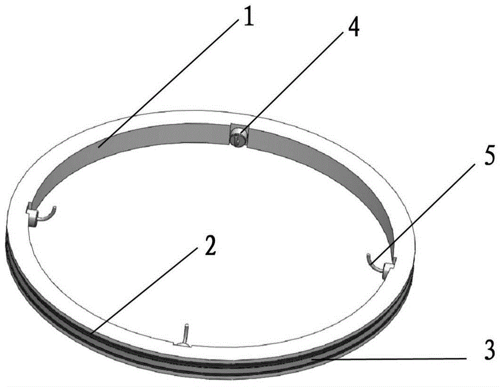
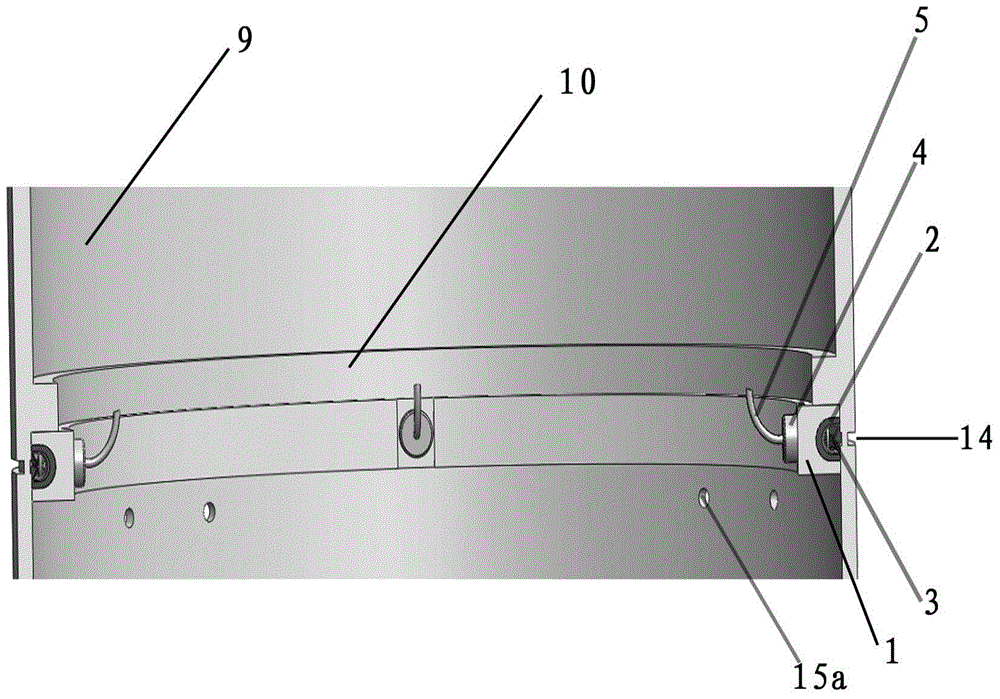
[0058] Such as figure 1 Shown is a perspective view of a specific product of the present invention. The main body of the device is a cutting assembly device adapted to the missile body. The cutting assembly device is a protective cover 1, a rubber protective cover 2, and a cutting cable 3 from outside to inside. Stress grooves are set on the part of the projectile to be cut, and the cutting components are aligned with the stress grooves for installation. 4 detonators 4 that are evenly distributed at 90° intervals along the 360° circle are installed on the protective cover and the rubber protective cover, and the detonators 4 are connected with detonating cables 5 .

[0059] Such as figure 2 Shown is an inside diagram of a specific product of the presen...


PUM


Abstract

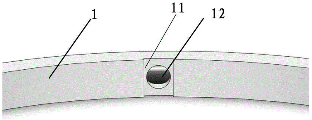
The invention discloses a cutting device for missile stage separation. The cutting device comprises a shield (1), a rubber shield (2), a cutting rope (3) and exploders (4); the inner edge, which is in contact with the rubber shield (2), of the cutting rope (3) is of a U-shaped structure, the outer edge of the cutting rope (3) is of a V-shaped structure, the opening of which is outward, the two structures are closed to form an annular closed cavity, and explosive is loaded in the cavity; the shield (1) is in contact with the rubber shield (2) to wrap the rubber shield (2) and the cutting rope (3); the inner edge of the shield (1) is provided with four grooves (11), which are evenly distributed at the interval of 90 degrees, and a mounting hole (12) which is connected with the cavity is formed in each groove (11) in order to mount and fix one of the exploders (4); detonating cables (5) are connected with detonation signal cables (8) through steering engine plug connectors, so that a signal can be transmitted to detonate the cables. The cutting device has the advantages of stable connection, high detonation synchronism, low destructiveness and full cutting when being used for missile stage separation.

Description

technical field [0001] The invention discloses a cutting device for separating missile stages, which belongs to the technical field of aviation machinery. Background technique [0002] For the missile system, in order to launch the effective carrier to the predetermined target, it is necessary to unlock and separate the stages and compartments that have completed the predetermined work. The separation and unlocking process is directly related to the success or failure of the missile to complete the flight mission. Therefore, the interstage separation device of the missile is a key component of the missile. The inter-stage separation device of the missile has to complete two different functions in actual work. Before separation, it is necessary to ensure the reliable connection of the two separation components; during separation, it is necessary to ensure the reliable separation of the two separation components, and it is necessary to ensure that there is no hazard affecting...

Claims


Application Information

Patent Timeline
IPC IPC(8): F42B15/36
Inventor 孙国权
Owner 北京威标至远科技发展有限公司
Learn More