Abutment reaming hole construction for optimizing deformation capability of integral abutment bridge

An integral abutment and abutment technology, which is applied in bridges, bridge parts, bridge construction, etc., can solve the problems of less rigid connections, inability to transmit force, and lack of flexibility, so as to improve the ability to withstand strong external impacts and The performance of the reaction force of the bridge structure, the load-bearing capacity will not decrease, and the effect of the force transmission structure will be improved

Inactive Publication Date: 2015-08-12
FUZHOU UNIV
View PDF9 Cites 2 Cited by
  • Summary
  • Abstract
  • Description
  • Claims
  • Application Information

AI Technical Summary

Problems solved by technology

[0002] The main girder of the integral abutment bridge is connected to the abutment as a whole, which has good integrity. However, under this structure, the longitudinal displacement of the upper part of the bridge due to factors such as temperature, creep shrinkage, and vehicle braking is mainly caused by its substructure. Compensation, which requires the abutment foundation of the substructure to have a good deformation capacity, in the current situation that domestic abutment foundations mostly use concrete piles, to improve the deformation capacity of such supporting piles, the common practice is to connect the piles with the bridge The holes around the abutment connection are reamed so that the pile has enough deformation space, but this method cannot transmit force due to the deformation space in the hole, so that the pile top and the abutment can only be connected in a rigid connection to strengthen its bearing capacity. However, there are few connection methods for rigid connections, lack of flexibility, and the improvement of the deformation capacity of the abutment foundation is limited. How to further optimize the deformation capacity of the abutment foundation is a research direction for those skilled in the art

Method used


Image

  • Abutment reaming hole construction for optimizing deformation capability of integral abutment bridge
  • Abutment reaming hole construction for optimizing deformation capability of integral abutment bridge
  • Abutment reaming hole construction for optimizing deformation capability of integral abutment bridge

Examples


Embodiment 1

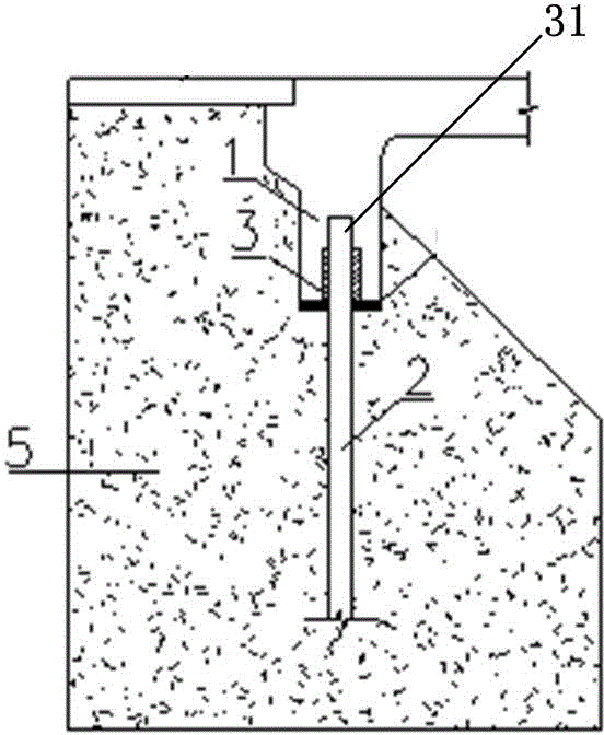
[0032] When the abutment reaming structure adopts such as Figure 4 The sliding connection shown, in daily use, the bridge is slowly deformed in the horizontal direction due to the temperature load, and its deformation pressure acts on the support pile 2 through the abutment reaming hole 30 of the abutment 1, because the abutment reaming hole 30 and the support There is a deformation layer 3 between the piles 2. The deformation layer 3 first produces elastic deformation under huge pressure, and disperses the pressure to reduce the horizontal load borne by the supporting pile 2. Since the material of the deformation layer 3 has certain fluidity, the deformation layer 3 Under the huge pressure slowly produced by the temperature deformation of the bridge, the material in the deformation layer 3 in the direction of the pressure is gradually squeezed to the side and redistributed, resulting in plastic deformation. The horizontal deformation of the main body is compensated, so that ...

Embodiment 2

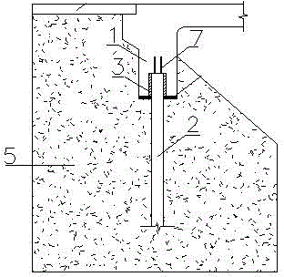
[0034] When the abutment reaming structure adopts such as image 3 As shown in the hinge joint, when an earthquake occurs, the bridge vibrates rapidly and greatly, and the vibration acts on the supporting pile 2 through the abutment reaming hole 30 of the abutment 1, because there is a deformation layer between the abutment reaming hole 30 and the supporting pile 2 3. Due to its elastic characteristics, the deformation layer 3 produces reciprocating deformation under a huge reciprocating load and effectively absorbs the load. The material of the deformation layer 3 has certain fluidity, which can disperse the impact force generated by huge vibrations, and effectively reduce the reciprocating load of the concrete pile foundation. Destruction under load. At this time, the connecting steel bar 7 at the top of the supporting pile 2 is deformed under the action of torsion, and the reciprocating load generated at the steel bar 7 due to the earthquake is eliminated by deformation, whi...


PUM


Abstract

The invention discloses an abutment reaming hole construction for optimizing deformation capability of an integral abutment bridge. The construction comprises an abutment reaming hole, a deformation layer and supporting piles. The abutment reaming hole is arranged at the supporting surface of the bottom part of an abutment. The lower ends of the supporting piles are buried in the ground, and the upper ends stretch into the abutment reaming hole. The tops of the piles support the abutment. The deformation layer is arranged between the abutment reaming hole and the supporting piles arranged in the hole. The mode of connection of the tops of the supporting piles and the abutment is rigid connection or flexible connection. The methods used in flexible connection include hinge connection and slide connection. The force bearing characteristic of the abutment reaming hole construction is optimized so that force bearing performance is guaranteed and deformation capability of the abutment bridge is enhanced.

Description

technical field [0001] The invention relates to the construction field, in particular to an abutment reaming structure for optimizing the deformation capacity of an integral abutment bridge. Background technique [0002] The main girder of the integral abutment bridge is connected to the abutment as a whole, which has good integrity. However, under this structure, the longitudinal displacement of the upper part of the bridge due to factors such as temperature, creep shrinkage, and vehicle braking is mainly caused by its substructure. Compensation, which requires the abutment foundation of the substructure to have a good deformation capacity, in the current situation that domestic abutment foundations mostly use concrete piles, to improve the deformation capacity of such supporting piles, the common practice is to connect the piles with the bridge The holes around the abutment connection are reamed so that the pile has enough deformation space, but this method cannot transmi...

Claims


Application Information

Patent Timeline
IPC IPC(8): E01D19/02
CPCE01D19/02
Inventor 陈宝春布鲁诺·布里斯杰拉黄福云钱海敏付毳庄一舟
Owner FUZHOU UNIV
Why Eureka
Try Eureka