Multi-field coupling penetration test device and method for cracked rock
A permeability test device, rock technology, applied in the direction of measurement device, permeability/surface area analysis, suspension and porous material analysis, etc., can solve the problem of few experimental conditions, monotonous design functions, and the inability to further comprehensively explore the evolution of fractured rock permeability characteristics Mechanism and other issues to achieve the effect of improving test accuracy
- Summary
- Abstract
- Description
- Claims
- Application Information
AI Technical Summary
Problems solved by technology
Method used
Image
Examples
Embodiment 1
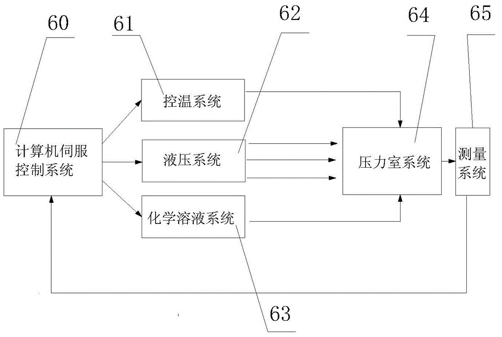
[0047] figure 1 It is a schematic diagram of the principle of a multi-field coupling penetration test device for fractured rocks. The present invention consists of a computer servo control system 60, a hydraulic system 62, a temperature control system 61, a chemical solution system 63, a pressure chamber system 64 and a measurement system 65. Among them, the computer servo control system applies multi-field coupling test conditions (such as heating, cooling, confining pressure, axial pressure, osmotic pressure, chemical field) to the pressure chamber system by controlling the hydraulic system, temperature control system and chemical solution system to measure The system measures the relevant quantities in each system, feeds back the results to the computer system, and makes relevant operations through the software settings in the computer until the end of the test.
[0048] The present invention can automatically control the test through the computer servo system, and can also...
Embodiment 2
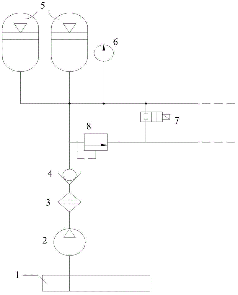
[0058] Hydraulic system: such as figure 2 As shown, the oil in the oil tank 1 is pumped into the accumulator 5 by means of the electric motor oil pump 2, and a check valve 4 is installed in the pipeline to ensure that the oil cannot flow in reverse. When the hydraulic oil was charged into the accumulator 5, the nitrogen in the accumulator 5 was compressed to store the pressure, and the pressure gauge 6 would display the hydraulic pressure in the accumulator 5. If the pressure in the accumulator 5 is greater than the set value, the excess oil will flow back to the tank through the overflow valve 8. If hydraulic oil needs to be increased in the hydraulic system, the gas expansion force in the accumulator 5 pushes the hydraulic oil out to supplement the hydraulic system.
Embodiment 3
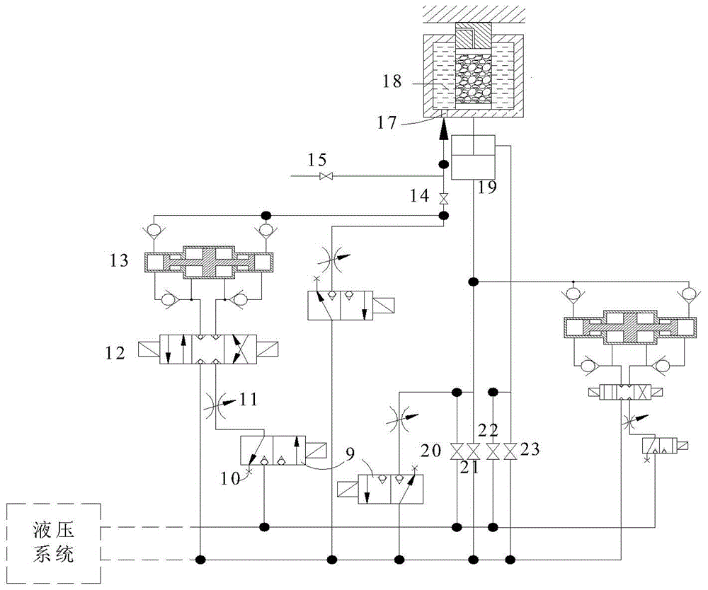
[0060] Loading and unloading of confining pressure: such as image 3 , Figure 5 as shown,
[0061] During the test, manually open the confining pressure oil supply valve 14, the hydraulic oil in the hydraulic system will pass through the two-position three-way valve 9, the electro-hydraulic proportional valve 11, the two-position four-way valve 12, the pressure-bearing oil cylinder 13, the confining pressure oil supply valve 14 and the confining pressure oil inlet hole 17 are filled into the confining pressure chamber 18, when oil emerges from the air outlet channel 34 of the confining pressure chamber, the confining pressure chamber 18 is filled with confining pressure oil, and the confining pressure oil supply valve is immediately closed 14. Close the air outlet channel 34 of the confining pressure chamber. When the confining pressure is applied, the confining pressure oil supply valve 14 is opened, and the hydraulic oil source will gradually pressurize the confining pres...
PUM
 Abstract
Description
Claims
Application Information
 - R&D
- Intellectual Property
- Life Sciences
- Materials
- Tech Scout
- Unparalleled Data Quality
- Higher Quality Content
- 60% Fewer Hallucinations
Browse by: Latest US Patents, China's latest patents, Technical Efficacy Thesaurus, Application Domain, Technology Topic, Popular Technical Reports.
© 2025 PatSnap. All rights reserved.Legal|Privacy policy|Modern Slavery Act Transparency Statement|Sitemap|About US| Contact US: help@patsnap.com


