Seed crystal jointing structure for oriented solidification of cast ingots

A technology of directional solidification and seed crystal, which is applied in the field of silicon crystal manufacturing, can solve problems such as poor process tolerance performance, affecting the quality of single crystal ingots, splicing and deformation of seed crystals, etc., to increase the proportion of single crystal area and improve photoelectric conversion Efficiency, performance-enhancing effects

Inactive Publication Date: 2015-08-05
NANTONG UNIVERSITY
View PDF5 Cites 8 Cited by
  • Summary
  • Abstract
  • Description
  • Claims
  • Application Information

AI Technical Summary

Problems solved by technology

[0005] However, the inventor has found through experiments that the above-mentioned method still has defects.
Although the bevel splicing reduces the generation of gaps to a certain extent, due to the smooth bevel, the seed crystal splicing method may cause deformation of the seed crystal splicing due to pressure during the seed crystal splicing and silicon filling process, thus affecting the quality of the subsequent single crystal ingot. , the splicing of the seed crystal puts forward very high technical requirements, and the process tolerance performance becomes worse
At the same time, during the heating process, the tightly arranged seed crystals may warp due to thermal expansion, and the splicing gap between the seed crystals will become larger, resulting in the proliferation of subsequent crystal dislocations, or the formation of polycrystalline grain boundaries

Method used


Image

  • Seed crystal jointing structure for oriented solidification of cast ingots
  • Seed crystal jointing structure for oriented solidification of cast ingots

Examples


Embodiment Construction

[0019] The present invention will be further described below in conjunction with the accompanying drawings and specific embodiments.

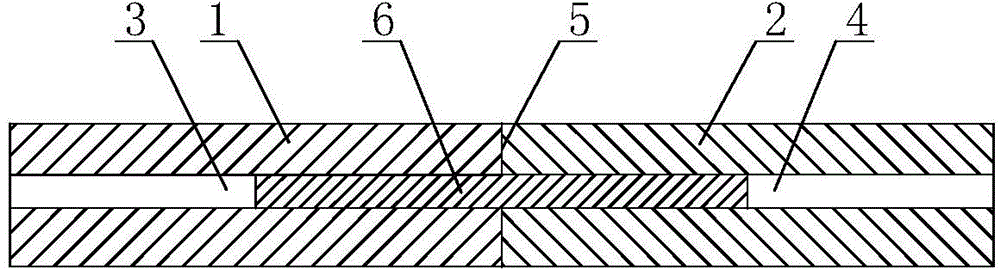
[0020] like figure 1 , figure 2 As shown, the seed crystal splicing structure for directional solidification ingot in the embodiment of the present invention includes elongated plate-shaped seed crystal blocks 1, 2 that are spliced ​​with each other, and the splicing surface 5 between adjacent seed crystal blocks 1, 2 is a crucible In the vertical plane at the bottom, the seed crystal block 1 is provided with a transverse cylindrical hole 3 perpendicular to the splicing surface 5, and the seed crystal block 2 is provided with a transverse cylindrical hole 4 perpendicular to the splicing surface 5, after the seed crystal blocks 1 and 2 are spliced ​​together The horizontal cylindrical holes 3 and 4 are paired to form an elongated cylindrical cavity, a silicon rod 6 is inserted into the cylindrical cavity, and the gap between the silicon rod 6 ...


PUM

PropertyMeasurementUnit
pore sizeaaaaaaaaaa

Abstract

The invention relates to a seed crystal jointing structure for oriented solidification of cast ingots. The seed crystal jointing structure comprises jointed seed crystal blocks, wherein jointing surface betweens two seed crystal blocks are planes which are vertical to the bottom of a crucible; a transverse columnar hole vertical to the jointing planes is formed in each seed crystal block; after adjacent seed crystal blocks are jointed, the transverse columnar holes are jointed to form a bar-shaped columnar cavity; a silicon rod inserts the columnar cavity. The transverse columnar holes are formed in the seed crystal blocks; two ends of the silicon rod insert the columnar holes of adjacent seed crystal blocks, thus jointing of the seed crystal blocks is realized; the jointing manner has a mortise-and-tenon jointing structure, thus lamination of the seed crystal jointing surfaces is improved. During heating, seed crystal at the edges is expanded by heating and the mortise-and-tenon jointing structure becomes relatively tight, thus expanding of seams caused by wrapped edges of the seed crystal blocks is prevented. The silicon rod and the columnar holes can be processed at one time through a drilling machine and are easily realized in industries; the jointing (inserting) method is simple, is easy to be mastered by operators and has relatively high practical value.

Description

technical field [0001] The invention relates to a splicing structure of seed crystals for directional solidification ingots, and belongs to the field of silicon crystal manufacturing. Background technique [0002] In recent years, silicon single crystal and silicon polycrystalline have been widely used in photovoltaic solar cells, liquid crystal display and other fields. At present, the common manufacturing method of silicon-like single crystal is the directional solidification method. In this method, cuboid seed crystals are laid on the bottom of the flat-bottomed crucible, and the seed crystals are arranged regularly to form a seed crystal layer. The silicon material is placed in a flat-bottomed crucible and laid on the seed crystal layer. Through the temperature control in the melting stage, after the silicon material is melted, the seed crystal gradually melts from the surface in contact with the silicon liquid, and then the directional growth of the silicon ingot is re...

Claims


Application Information

Patent Timeline
Patent Type & Authority Applications(China)
IPC IPC(8): C30B11/14C30B29/06
Inventor 王强花国然李俊军邓洁
Owner NANTONG UNIVERSITY
Why Eureka
Try Eureka