Vibrating screen

A technology of sieve screen and screen frame, which is applied in the field of high-efficiency vibrating sieve screen, can solve the problems of high plugging rate, large sieving particle size control error, poor screening accuracy, etc., and achieve low plugging rate , saving energy consumption, low manufacturing cost effect

Pending Publication Date: 2015-08-05
WUHAN MOLINHAN ELECTROMECHANICAL EQUIP +1
View PDF7 Cites 1 Cited by
  • Summary
  • Abstract
  • Description
  • Claims
  • Application Information

AI Technical Summary

Problems solved by technology

There are two major defects in the existing screens: high plugging rate and large sieving particle size control error
This technology only limitedly reduces the plugging phenomenon, but the screening accuracy is still very poor

Method used


Image

  • Vibrating screen
  • Vibrating screen
  • Vibrating screen

Examples


Embodiment Construction

[0034] The application will be further described below in conjunction with the accompanying drawings.

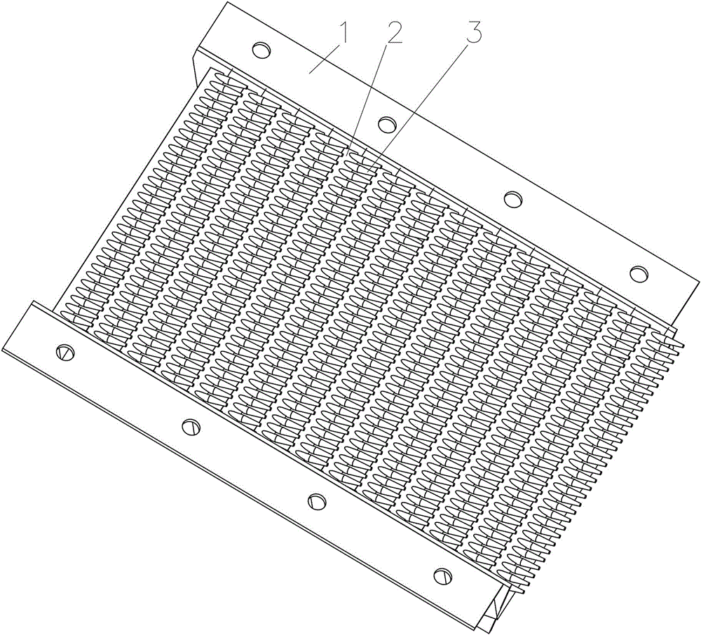
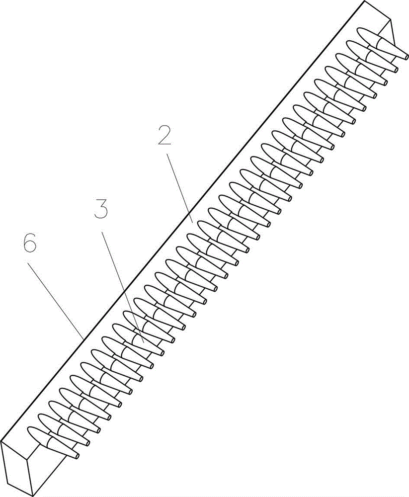
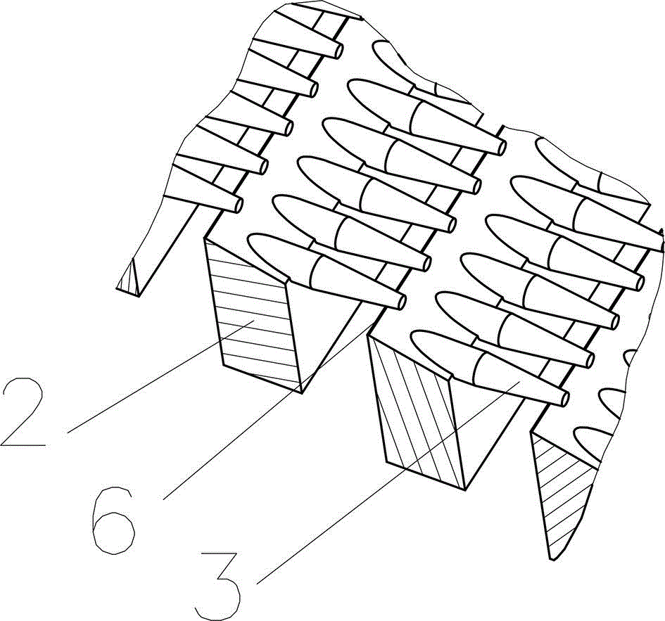
[0035] A vibrating screen has a screen frame 1 on both sides, and bolt holes are arranged on the screen frame 1 . The ends of several sieve teeth 3 are evenly distributed in the same direction and fixed on the beam 2 side by side. constitute a sieve unit. The rear part of the sieve tooth 3 is consolidated with the beam 2, and the end part is suspended. The sieve tooth 3 is integrally made of alloy steel, which has high strength and toughness. The front portion of the sieve teeth 3 is a conical surface with a cone angle of 18°. The cylindrical surface in the middle of the sieve teeth 3 is connected with the cone surface, and there is a cylindrical surface with a slightly larger diameter than the cylindrical surface at the tail. On the crossbeam 2 there are mesh hole 21 and steps 27 uniformly distributed parallel to the diameter of the tail of the mesh 3 and the raised ste...


PUM


Abstract

The invention discloses a vibrating screen comprising a screen frame. More than one screen teeth are arranged on the frontal surface of a cross beam side by side in the same direction to form a screen strip unit. The back parts of the screen teeth are fixedly connected with the cross beam; and the ends are suspended. The structure adopts a whole single material; the front part at least has one section as a rotating curved surface structure; the cross section thereof is gradually decreased from the back end to the front end; an included angle between the tangent line of at least one point of the generatrix, coplanar with a rotating shaft, of the rotating curved surfaces of the screen teeth and a revolving shaft is greater than 5.5 degrees and smaller than 45 degrees; multiple screen strip units are arranged in a front-back manner, and the screen teeth are fixedly connected to the screen frame in the same direction; the screen teeth of the screen strip units at the back part are positioned above the cross beams of the previous screen strip units; and the front ends of the screen teeth are beyond of the back surfaces of the cross beams of the previous screen strip units. The screen teeth are rigid, and the surfaces are smooth curved surfaces, so that the vibrating screen has the advantages of high screening precision and low hole blockage rate, and totally solves the defects in the prior art.

Description

technical field [0001] The invention belongs to the technical field of vibrating sieving, in particular to a high-efficiency vibrating sieve mesh. Background technique [0002] Vibrating screen is the main equipment for screening bulk materials. It is widely used in mining, building materials, metallurgy and other industries. The current screen forms mainly include round hole sieve plate, oblong herringbone hole sieve plate, woven screen, comb tooth screen, elastic bar screen and so on. Due to the mesh structure. There are two major defects in the existing sieves: high hole blocking rate and large sieving particle size control error. Affect production and waste energy. [0003] When using a vibrating screen equipped with a round-hole sieve plate, a comb-teeth sieve, an oblong herringbone-hole sieve, and a woven sieve for screening operations, since the sieve holes are rigid, the particle size control of the underscreen is more accurate. , no material particles larger th...

Claims


Application Information

Patent Timeline
Patent Type & Authority Applications(China)
IPC IPC(8): B07B1/28B07B1/46
CPCB07B1/28B07B1/4609
Inventor 姜秀萍胡娟姜本熹
Owner WUHAN MOLINHAN ELECTROMECHANICAL EQUIP
Why Eureka
Try Eureka