
Electrical equipment appearance abnormity detection method based on image comparison

A technology for anomaly detection and power equipment, applied in image enhancement, image analysis, image data processing, etc.

Active Publication Date: 2015-07-29
STATE GRID INTELLIGENCE TECH CO LTD
View PDF2 Cites 90 Cited by
  • Summary
  • Abstract
  • Description
  • Claims
  • Application Information

AI Technical Summary

Problems solved by technology

[0005] First, the current inspection robot equipped with image processing and recognition technology has limited detection functions, and most of the images taken by inspection still need to be observed and analyzed by operators at any time, which increases the burden on the on-site staff;
[0006] Second, some existing power equipment anomaly recognition algorithms need to establish different image template libraries for different equipment in substations / converter stations. The anomaly detection of different types of equipment requires the design of different image recognition algorithm frameworks, which consumes a lot of time and effort. manpower;
[0007] Third, using image processing and recognition technology to detect abnormalities in power equipment, it is first necessary to locate the position of the equipment to be inspected in the image. The accuracy of equipment positioning will directly affect the recognition effect of power equipment status detection, and positioning deviation will cause False positives and missed negatives occur, and there are certain security risks

Method used


Image

  • Electrical equipment appearance abnormity detection method based on image comparison
  • Electrical equipment appearance abnormity detection method based on image comparison
  • Electrical equipment appearance abnormity detection method based on image comparison

Examples


Embodiment Construction

[0075] The present invention will be further described below in conjunction with the drawings and embodiments.

[0076] Such as figure 1 As shown, the method steps of the present invention are as follows:

[0077] The first step is to read in the current patrol image by searching the patrol database I 2 Compared with the historical inspection image I 1 , The two images are the images taken by the inspection robot at the same stopping point and at the same angle.

[0078] Step 2: Images taken at historical moments I 1 For reference, for image I 2 Perform image normalization processing to get the normalized image I 2 , The normalization formula is:

[0079] I 2 ( r ) = σ 1 σ 2 { I 2 ( r ) - μ 2 } + μ 1

[0080] Among them, μ 1 For image I 1 Mean gray value, μ 2 For image I 2 Mean gray value of σ 1 For image I 1 The gray-scale variance, σ 2 For image I 2 The gray-scale variance, I 2 (r) is the normalized image I 2 Gray ...


PUM


Abstract

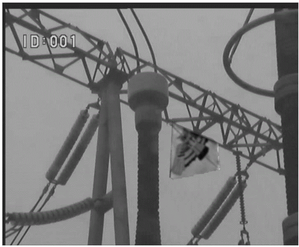
The invention discloses an electrical equipment appearance abnormity detection method based on image comparison. The electrical equipment appearance abnormity detection method includes normalizing an image photographed during current routing inspection, registering the image with an image photographed at the same position and angle during historical routing inspection, continuing region segmentation on the two registered images respectively, extracting a plurality of characteristics of each region image, fusing the characteristics, calculating difference between the corresponding characteristics of the two images, comparing the difference with a preset threshold value and judging whether the image photographed during current routing inspection is abnormal or not. The electrical equipment appearance abnormity detection method has the advantages that abnormity detection of different types of electrical equipment is achieved under the same algorithm framework; the two images photographed at the same stop and angle by a routing inspection robot during different moments are compared, region changes of the images, with the same content, respectively photographed at a current moment and during historical routing inspection are judged, and accordingly, abnormities, such as damage and foreign-matter suspension, of the electrical equipment are detected.

Description

Technical field [0001] The invention relates to a method for detecting abnormal appearance of power equipment based on image comparison. Background technique [0002] With the continuous expansion of my country's power network, the safe and reliable operation of substations / converter stations is essential, and the operating status of power equipment is one of the key factors that determine its safe and stable operation. Daily observation of the status of equipment in substation / converter station is one of the most content and one of the most arduous tasks in the inspection process. The main inspection contents of the station staff include: foreign objects hanging, equipment damage, deformation, oil leakage of oil storage equipment, and surface Stains etc. [0003] With the development of computer science, image processing and recognition technology has achieved rapid development in theoretical research and practical application. Based on the application of image processing and rec...

Claims


Application Information

Patent Timeline
IPC IPC(8): G06T7/00G06T7/40G06T3/00
CPCG06T7/0008G06T2207/20021G06T2207/10024G06T2207/30108G06T3/14
Inventor 张旭王海鹏李丽肖鹏慕世友任杰傅孟潮栾贻青李建祥赵金龙王万国
Owner STATE GRID INTELLIGENCE TECH CO LTD
Learn More