
Method for forming cutting surface in deep hole blasting

A deep hole blasting and cutting surface technology, which is applied in blasting and other directions, can solve the problems of affecting mining production efficiency, poor cutting effect on both sides of small wells, and difficult hole layout in deep holes, so as to realize integrated cutting and mining operations and simplify mining and cutting Process, the effect of improving cutting efficiency

Active Publication Date: 2015-07-29
JIUQUAN IRON & STEEL GRP
View PDF5 Cites 9 Cited by
  • Summary
  • Abstract
  • Description
  • Claims
  • Application Information

AI Technical Summary

Problems solved by technology

Affected by manual excavation and cutting engineering, the deep hole drilling process of cutting work and the mining and falling process cannot form an organic connection, which affects the production efficiency of mining
[0004] 2. The traditional cutting method adopts manual excavation of the patio, which takes a long time for construction and low cutting efficiency
[0005] 3. Due to the traditional cutting method, the operator works in the patio, a large amount of dust and water mist are generated during the rock drilling process, the air pollution is serious, and the working environment is harsh, which greatly affects the physical and mental health of the operators.
[0006] 4. The production cost of the traditional cutting method is high
[0007] 5. The traditional cutting method causes high ore loss at the cutting part
The cutting method of cutting the patio is adopted. Since both sides of the patio are solid, it is necessary to further expand the free surface after the deep hole blasting in the construction. However, the expansion of the free surface is affected by the small cutting surface and the large force of the deep hole. The two sides of the small well are cut Poor effect, low ore recovery rate
If chamber blasting is used for cutting, the ore blasting at the cutting part will be uneven and the recovery rate will be lower

Method used


Image

  • Method for forming cutting surface in deep hole blasting
  • Method for forming cutting surface in deep hole blasting

Examples


Embodiment 1

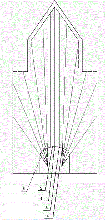
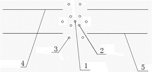
[0023] A method for forming a cutting surface in deep hole blasting. The setting of the blasting point includes a central charge hole 1, an empty hole 2, an auxiliary charge hole 3, a cutting fan hole 4, and a radiation center 5. The central charge hole 1 is located in the center of the hollow hole 2; the hollow hole 2 is parallel to the central charge hole 1; the auxiliary charge hole 3 is symmetrical about the central charge hole 1 and the two rows of cutting fan-shaped holes 4; the cutting fan-shaped hole 4 is Two rows of fan-shaped deep holes with a row spacing of 2000mm; the cutting fan-shaped holes 4 are two rows of fan-shaped blast holes, located on the left and right sides of the auxiliary charge hole 3; the radiation center 5 is located on the two radiation center points of the cutting fan hole 4 ;

[0024] In the blasting, the sequence of initiation is central charge hole 1 → auxiliary charge hole 3 → cutting fan hole 4; the cutting fan hole 4 is blasted to both sides w...


PUM


Abstract

The invention discloses a method for forming a cutting surface in deep hole blasting, and relates to the technical field of underground mining blasting. The structure comprises a central charge hole (1), an empty hole (2), an auxiliary charge hole (3), cutting scallop holes (4) and emission centers (5). The structure achieves the purpose of deep hole blasting cutting, a recovery cutting process is simplified, cutting efficiency is improved, cutting cost is reduced, benefits are remarkable, ore recovery rate is increased, recovery cost is reduced, the cutting scallop holes are distributed in the double emission centers, cutting effects are improved, a cutting operation environment is effectively improved, the physical and psychological health of staff is guaranteed, cutting and recovery are integrated in production, three-grade reserve remaining period can be reduced, and the fund utilization efficiency of a mining engineering is improved.

Description

Technical field [0001] The invention relates to the technical field of underground mining blasting, in particular to a method for forming a cutting surface in deep hole blasting. Background technique [0002] In the domestic cutting process of the non-pillar sublevel caving method, the initial cutting free surface is mostly formed by manually using pneumatic rock drilling equipment (YG90 or YT28 rock drill), constructing a cutting patio or cutting chamber blasting (called traditional cutting method) ). The method of manual excavation and cutting engineering has outstanding problems such as low production efficiency, high labor intensity, poor working environment, and high production cost, and affects the subsequent ore mining work. [0003] 1. The traditional manual construction cutting project is carried out between the deep-hole drilling and deep-hole sinking procedures, which is an indispensable preparation for the stoping work. Affected by the manual excavation and cutting en...

Claims


Application Information

Patent Timeline
Patent Type & Authority Applications(China)
IPC IPC(8): F42D1/00F42D3/04
Inventor 陈永祺程国华田宏海任国芳
Owner JIUQUAN IRON & STEEL GRP
Learn More