
A condensate collector for easy gas-liquid-solid separation

A gas-liquid-solid separation and condensate technology, which is used in gas/liquid distribution and storage, pipeline systems, mechanical equipment, etc. Realize problems such as gas recovery, and achieve the effect of reducing operating costs and transportation costs, reducing transportation difficulties, and improving gas purification rate

Active Publication Date: 2017-11-14
BC P INC CHINA NAT PETROLEUM CORP +2
View PDF6 Cites 0 Cited by
  • Summary
  • Abstract
  • Description
  • Claims
  • Application Information

AI Technical Summary

Problems solved by technology

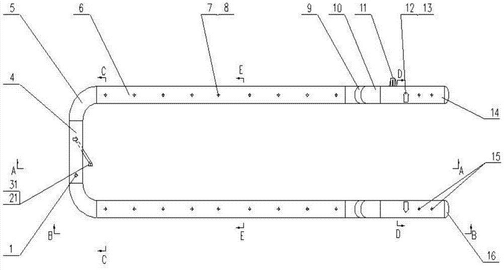
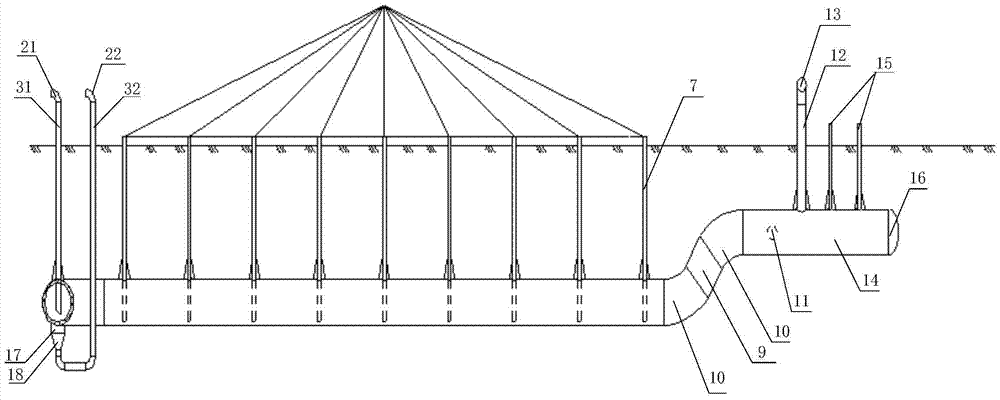
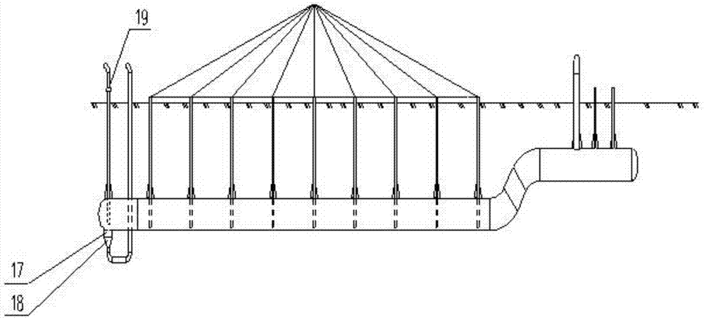
[0006] In order to solve the problems of incomplete pipeline purging existing in the condensate collector used for natural gas pipelines, the condensate and impurities cannot be completely discharged, the separation of gas, liquid and solid cannot be realized, and the gas recovery cannot be realized, etc., the present invention provides A condensate collector that is convenient for gas-liquid-solid separation, the condensate collector has a U-shaped symmetrical structure, and specifically includes a first loading pipeline connecting pipe, a second loading pipeline connecting pipe, a liquid collecting steel pipe, a first connecting pipe Steel pipe, purge pipeline connection pipe, second connection steel pipe, air inlet connection pipe, gas outlet connection pipe, third connection steel pipe, pipe cap, liquid collection tank connection pipe and different diameter joint; the two ends of the liquid collection steel pipe pass through the first bend The head is connected to the first connecting steel pipe; one end of the first loading pipeline connecting pipe extends vertically into the liquid collecting steel pipe, and the other end of the first loading pipeline connecting pipe connects to the second elbow; One end of the connecting pipe of the collecting tank is connected to the steel pipe for collecting liquid, and the other end of the connecting pipe of the collecting tank is connected with one end of the connecting pipe of the second loading pipeline through the reducing joint; The other end of the connecting pipe of the loading pipeline is connected to the third elbow; the connecting pipe of the purge pipeline extends vertically into the bottom of the first connecting steel pipe and is connected to the first connecting steel pipe; the first connecting steel pipe passes through The fourth elbow is connected to one end of the second connecting steel pipe, and the other end of the second connecting steel pipe is connected to one end of the third connecting steel pipe through a fifth elbow; the other end of the third connecting steel pipe is connected to The pipe cap is connected; the air inlet connecting pipe is horizontally connected to the third connecting steel pipe; one end of the air outlet connecting pipe is vertically connected to the third connecting steel pipe, and the other end of the air outlet connecting pipe Connect the sixth elbow; the inlet of the first loading pipeline connecting pipe and the inlet of the second loading pipeline connecting pipe are located on the same straight line; the purge pipeline connecting pipe has multiple

Method used


Image

  • A condensate collector for easy gas-liquid-solid separation
  • A condensate collector for easy gas-liquid-solid separation
  • A condensate collector for easy gas-liquid-solid separation

Examples


Embodiment Construction

[0019] The technical solutions of the present invention will be further described below in conjunction with the accompanying drawings and embodiments.

[0020] This embodiment provides a condensate collector that is convenient for gas-liquid-solid separation. The condensate collector is designed separately and assembled on site, that is, the connecting pipes and pipe fittings of the condensate collector are designed and processed separately, and then transported to On-site and on-site trunk steel pipes are welded with openings.

[0021] see Figure 1 to Figure 6 , the condensate collector that is convenient for gas-liquid-solid separation provided in this embodiment includes a liquid level gauge connecting pipe 1, a loading pipeline connecting elbow 21, a loading pipeline connecting pipe 31, a loading pipeline connecting pipe 32, and a loading pipeline connecting pipe Elbow 22, liquid collecting steel pipe 4, 90 degree elbow 5, connecting steel pipe 6, purge pipeline connecti...


PUM


Abstract

The invention discloses a condensate collector which is convenient for gas-liquid-solid separation, and belongs to the technical field of gas, condensate and impurity separation during pipeline pigging operations. The condensate collector has a U-shaped symmetrical structure, and specifically includes a first loading pipeline connecting pipe, a second loading pipeline connecting pipe, a liquid collecting steel pipe, a first connecting steel pipe, a purge pipeline connecting pipe, a second connecting steel pipe, and an inlet pipe. Gas port connection, gas outlet connection, third connection steel pipe, pipe cap, liquid sump connection and reducing joint. The condensate collector for gas-liquid-solid separation provided by the invention is easy to install, can improve the gas purification rate of the entire pipeline, reduce transportation difficulty, reduce operating costs and transportation costs, and can ensure stable gas supply and safety of equipment in the station.

Description

technical field [0001] The invention relates to the technical field of gas, condensate and impurity separation during pipeline pigging on-line and off-line, in particular to a condensate collector for easy gas-liquid-solid separation. Background technique [0002] The second phase of the Kazakhstan-China natural gas pipeline project starts from Beineu in Mangistau and terminates in Shymkent via Bazoi. It belongs to the second stage of the Central Asia natural gas pipeline. There is a big difference in technical indicators between Central Asia and my country's "Long-distance Natural Gas Pipeline Temperament Requirements" (Q / SY30). stricter. [0003] Condensate is produced during pigging operations and as natural gas travels along pipelines. Condensate and impurities will reduce the calorific value and transportation capacity of natural gas, which will not only increase the flow pressure drop and cause slug flow, but also accelerate the corrosion of pipelines and equipment by ...

Claims


Application Information

Patent Timeline
Patent Type & Authority Patents(China)
IPC IPC(8): F17D3/14
Inventor 赵振兴傅伟庆孟庆鹏张志强赵树炳彭常飞李凯楠郭磊梁奋飞胡春伟范欣付丽
Owner BC P INC CHINA NAT PETROLEUM CORP
Learn More