
Bidirectional overrunning clutch, speed control device and automatic speed control system

A technology of overrunning clutches and clutches, applied in the field of clutches, which can solve the problems of high manufacturing precision requirements, limited application places, and low service life, and achieve the effects of large transmission torque, long service life, and reduced cross-sectional size

Active Publication Date: 2015-07-29
傅元才
View PDF4 Cites 17 Cited by
  • Summary
  • Abstract
  • Description
  • Claims
  • Application Information

AI Technical Summary

Problems solved by technology

For the one-way and two-way overrunning clutches with internal and external transmission structures, the high-speed transmission is formed by balls, rollers or wedges and the cam working surface, which requires high manufacturing precision, low mechanical efficiency, and low service life. At the same time, there are still Due to the defect of large cross-sectional size, the application place is greatly restricted

Method used


Image

  • Bidirectional overrunning clutch, speed control device and automatic speed control system
  • Bidirectional overrunning clutch, speed control device and automatic speed control system
  • Bidirectional overrunning clutch, speed control device and automatic speed control system

Examples


Embodiment 1

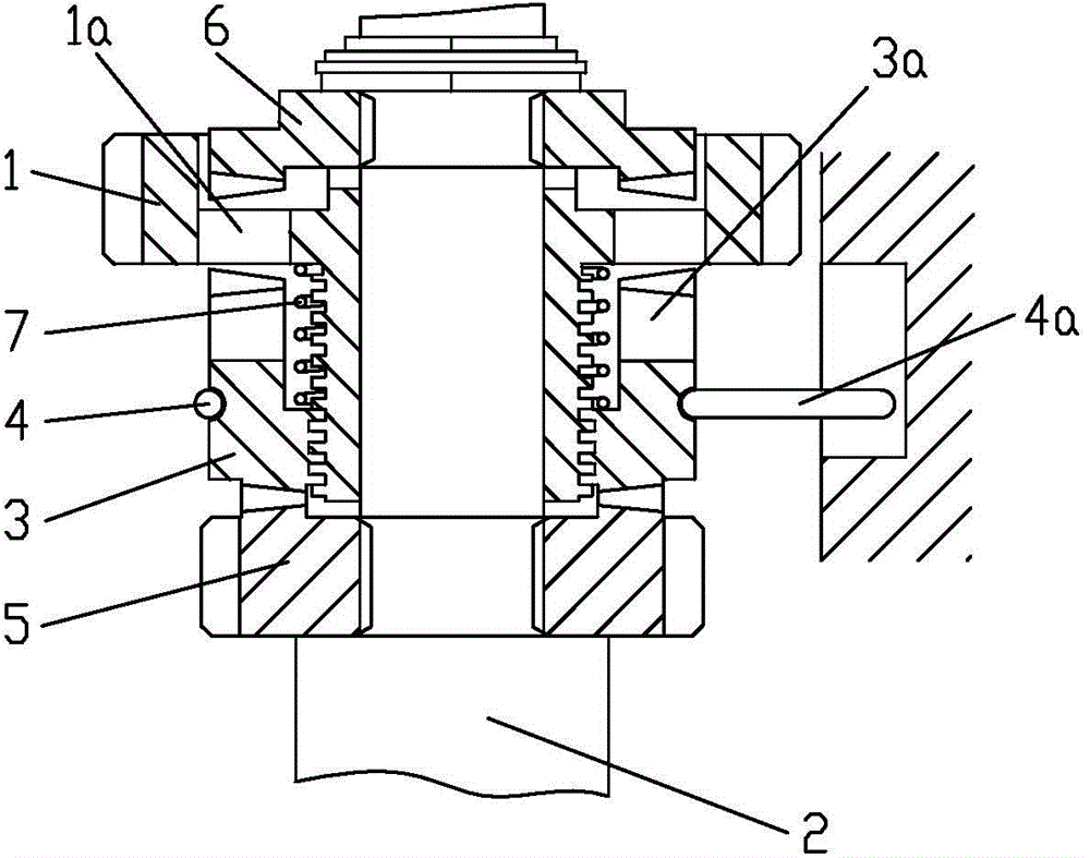
[0036] Example 1 see figure 1 , a two-way overrunning clutch, including a disc-shaped driving part 1 rotatably set on a shaft-shaped follower 2, one end journal of the driving part 1 is fitted with a helical spline sleeve 3 through a helical spline, and the helical spline The sleeve 3 is connected with a brake device that applies frictional resistance thereto; the brake device includes a C-shaped collar 4 with a collar shank 4a, and the C-shaped collar 4 is held on the helical spline sleeve 3 by a C-shaped clamping portion. The ring groove is provided; the C-shaped collar 4 is provided with a U-shaped collar handle 4a, and the U-shaped two free ends of the collar handle 4a are fixedly connected with the C-shaped two free ends of the C-shaped collar 4, and the collar handle 4a is used to prevent the C-shaped collar 4 from rotating synchronously with the helical spline sleeve 3 through the stationary component; the driven part 2 is fixedly connected with the first driven disc 5 ...

Embodiment 2

[0038] Example 2 see figure 2, the structure of the first end meshing clutch is composed of the intermeshing end teeth on the transition plate 8 and the driven member 2, and the transition plate 8 is connected to one end of the helical spline sleeve 3 through a one-way overrunning clutch 8a. Wherein, the intermeshing end teeth on the transition plate 8 and the driven member 2 may be right-angled triangular one-way teeth, isosceles triangles or isosceles trapezoidal two-way teeth.

[0039] The rest of the structure of this embodiment is the same as that of Embodiment 1, and will not be repeated here.

Embodiment 3

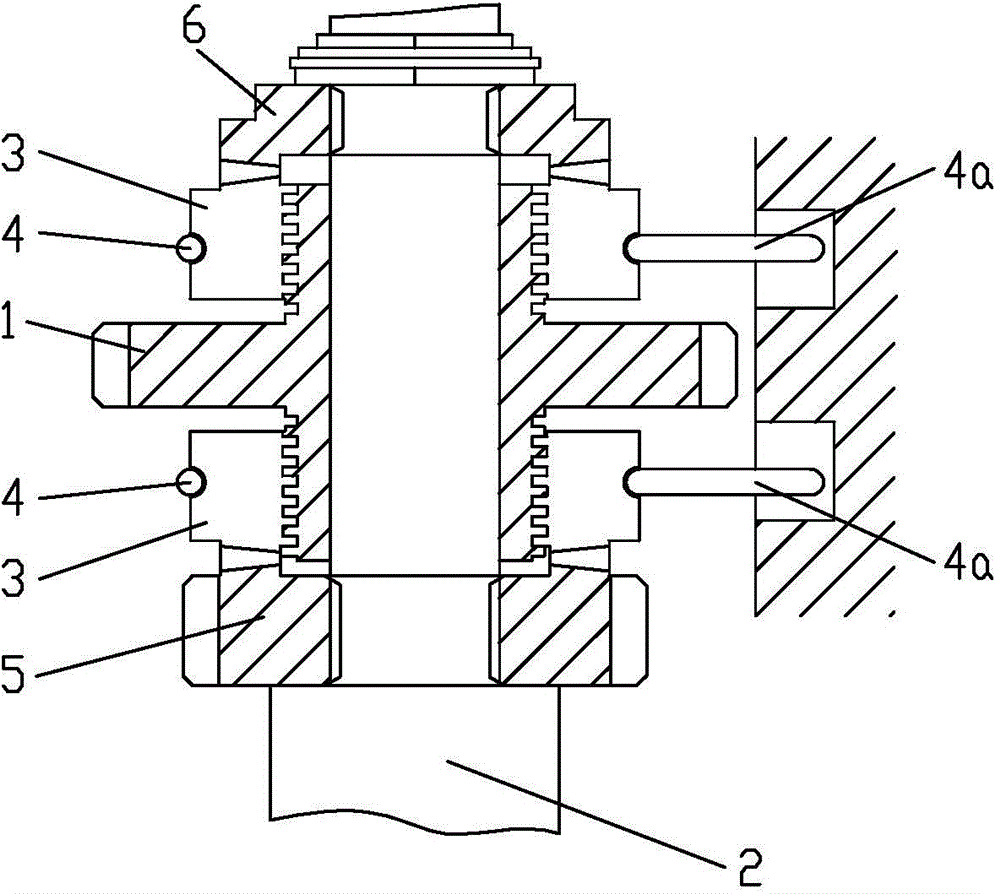
[0040] Embodiment 3 see image 3 , the helical spline sleeve 3 is provided with two fittings on the journals at both ends of the active member 1, the external splines of the journals at both ends of the active member 1 have the same rotation direction, and the two helical spline sleeves 3 are respectively The first end face meshing clutch structure and the second end face meshing clutch structure are formed with the first driven disc 5 and the second driven disc 6 .

[0041] The rest of the structure of this embodiment is the same as that of Embodiment 1, and will not be repeated here.


PUM


Abstract

The invention discloses a bidirectional overrunning clutch, a speed control device and an automatic speed control system. The bidirectional overrunning clutch comprises a disc-shaped driving part, wherein the disc-shaped driving part can rotatably sleeve a shaft-shaped driven part; a spiral spline sleeve is in spiral spline fit with a journal of the driving part, and a braking device which is used for applying frictional resistance to the spiral spline sleeve is connected to the spiral spline sleeve; a first end surface engagement clutch structure and a second end surface engagement clutch structure are formed between the spiral spline sleeve and the driven part, and the first end surface engagement clutch structure and the second end surface engagement clutch structure are respectively used only for the spiral spline sleeve to drive the driven part to synchronously rotate clockwise and anticlockwise; a bidirectional clutch structure is formed between high and low-speed driven gears of the speed control device and the automatic speed control system. The bidirectional overrunning clutch has the beneficial effects of small cross-sectional dimension, convenience in application, high mechanical efficiency, strong loading capability and long service life; two-gear automatic transmission and reverse output can be realized by the speed control device.

Description

technical field [0001] The invention relates to a clutch, in particular to a two-way overrunning clutch, a speed change device and an automatic speed change system. Background technique [0002] In automatic shifting transmission devices, one-way overrunning clutches are commonly used, also known as one-way devices, two-way overrunning clutches, controllable overrunning clutches, etc. The active part of the one-way overrunning clutch can drive the driven part to rotate in one direction in the set direction. Similarly, the driven part can drive the active part to rotate in the reverse direction; the active part of the two-way overrunning clutch can drive the driven part to rotate in the forward and reverse directions. But the driven part cannot drive the active part to rotate. For the one-way and two-way overrunning clutches with internal and external transmission structures, the high-speed transmission is formed by balls, rollers or wedges and the cam working surface, which...

Claims


Application Information

Patent Timeline
Patent Type & Authority Applications(China)
IPC IPC(8): F16D41/04F16H3/10
Inventor 傅元才刘洪
Owner 傅元才
Learn More