Slim linear LED lighting device

a technology of led lighting and linear lamps, which is applied in the direction of semiconductor devices for light sources, elongated light sources, light and heating apparatus, etc., can solve the problems of low light utilization factor, insufficient luminous intensity, and difficulty in designing or adopting streamlined or confined space vehicular lamps

Active Publication Date: 2020-12-10
EXCELLENCE OPTO INC
View PDF0 Cites 4 Cited by
  • Summary
  • Abstract
  • Description
  • Claims
  • Application Information

AI Technical Summary

Benefits of technology

The present invention provides a slim linear LED lighting device that solves the technical problems of existing LED light sources in high-quality vehicular lamps. The lighting device uses a special LED bar with a continuously and visually uniform linear light source that is different from granular LED packages. The LED bar has a condensing lens structure and is designed to enhance the effective utilization factor of the light entering the light blade and improve the luminous intensity in the center direction to meet the light distribution requirements of vehicular lamps. The width and height of the light source are less than 2 mm, suitable for a vehicular lamp with a thin light blade. The LED bar contains a plurality of same kind of LED chips regularly and closely arranged in a line or lines on the upper layer of a substrate with a pitch of 0.2 mm to 3.0 mm. The LED bar has a small cross-sectional dimension, increasing the effective utilization factor of the light and enabling a lower total flux of light to meet the photometry regulations. The slim linear LED lighting device can also improve the shortcomings of existing LED-based light sources, such as visually non-uniform brightness or obvious granular bright spots.

Problems solved by technology

However, these additional optical components would cause the lamp body to become larger or thicker, resulting in that it is difficult to be designed or adopted to streamlined or confined-space vehicular lamps.
Due to the presence of secondary lenses or diffusers, the cross-sectional dimensions of such LED tube lamps are therefore too large to be directly used in vehicular lamps with limited space and complicated structures.
These conventional LED light strips are not suitable for use on vehicular lamps that have specific light distribution requirements and demand of high luminous intensities to be operated in the daytime, such as daytime running lamp, turn signal lamps, etc.
However, the size of the LED light module is increased and the light intensity in the center direction is greatly reduced, and it is thus only suitable for general illumination and cannot be applied to linear vehicular lamps.
Using the packaged LED as the light source would lead to that the size and spacing of the light source are relatively large.
It is still difficult to achieve visually uniform illumination even if the silicone layer is added to make the LED light diffused.
The silicone light-emitting surface is a flat design, and thus lacks a light condensing effect and results in a low luminous intensity in the center direction, which is not suitable for the requirements of the aforementioned vehicular lamp photometry regulations.
However, since the light of the LED light source only enters from the end or side of the light guide, the long length of the light guide and the bending of the light guide due to the design of the vehicular lamp would result in a visually uneven light distribution.
In addition, because of the limited number of light sources, the shortcomings of the design of vehicular lamps formed of the light guide are that the lighting cannot be segmented or partitioned, and cannot meet the requirements of the animated lighting function.
However, the amount of heat generated by the LED light source is also increased, and the problem of heat dissipation and cost increase thus become unavoidable in such case.
There is always an air gap between the LED light source and the secondary lens in such design, which will result in the conventional Fresnel loss, lowering the utilization factor of the LED light.
When the light blade of a vehicular lamp is thin, the sidelight of the LED light source is escaped from the light blade, which deteriorates the effective utilization factor of the LED light.
How to firmly fix the secondary lens on the light bar in the application of vehicular lamps which requires vibration resistance will also be a technical problem.
Even if the secondary lens fixing structure design has no problem, the width of the light bar becomes wider due to the fixing structure, and the requirements for the streamlined and confined-space vehicular lamp are no longer satisfied.

Method used


Image

  • Slim linear LED lighting device
  • Slim linear LED lighting device
  • Slim linear LED lighting device

Examples


second embodiment

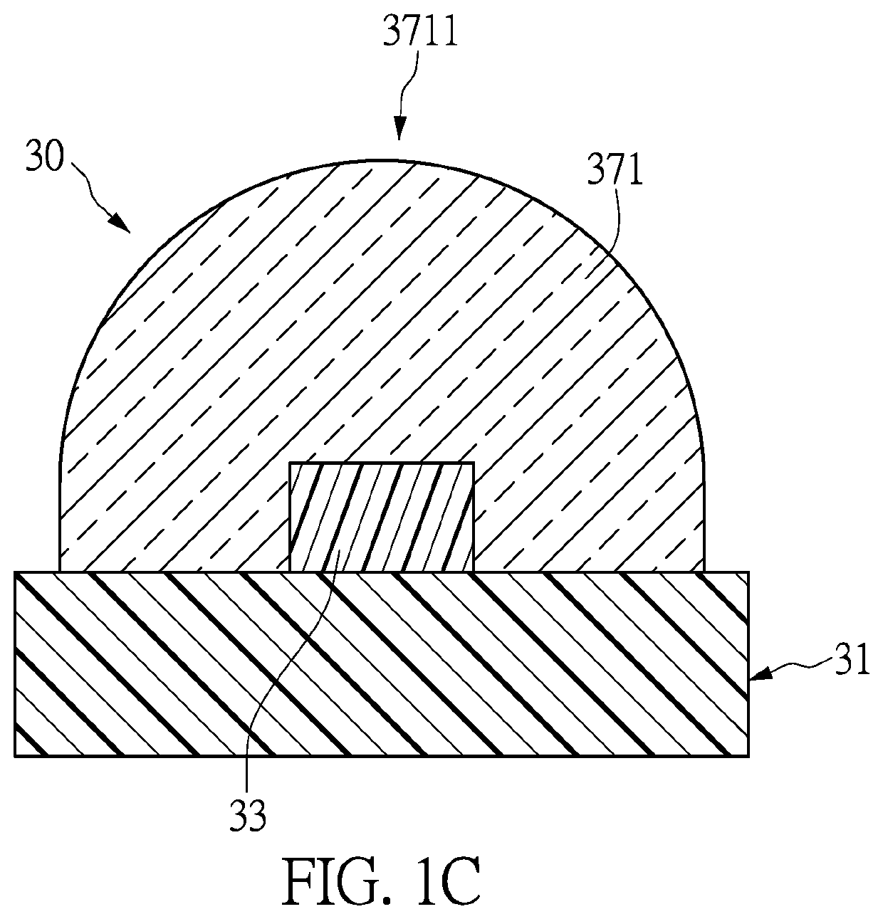
[0041]FIG. 2A and FIG. 2B disclose the design of the substrate 31a for the LED Bar 30a of the slim linear LED lighting device 1 of the The substrate 31a consists of a designed layout (FIG. 2A) of the conductive layer on the front surface for the mounting and wire bonding (if it is necessary) of all LED chips, and another designed layout (FIG. 2B) of the conductive layer on the bottom surface for surface mounting and thermal dissipation of the LED Bar. In this embodiment, the LED Bar 30a is designed with a circuit in which four LED chips 331, 332, 333, 334 are arranged at equal pitches, and four LED chips are connected in series. The circuit symbol is as shown in FIG. 2C. The LED chips connected in series is only an embodiment, and the present invention is not limited thereto. That is, the present invention can also adopt a circuit design in which all the LED chips are electrically connected in parallel or independently, or in a mix of in series and in parallel. The LED chips 331, 3...

fifth embodiment

[0048]FIG. 9 is the slim linear LED lighting device 1c of the present invention, which comprises a printed circuit board 20c on which a plurality of LED Bars 30c, a plurality of different LED Bars 30g, a control IC (not shown in the figures), an IC for driving LED (not shown), and a connector (not shown) are provided. The LED Bar 30g contains a small number of LED chips 33 (two LED chips 33 employed in this embodiment) and has a short length. In the slim linear LED lighting device 1c of the embodiment, the printed circuit board 20c is a flexible printed circuit board (FPCB), so that the portion where the short LED Bars 30g are mounted has better bending characteristics and can be coupled with a light blade (not shown) having a portion of curved shape. The LED Bars 30c contain more LED chips 33 (four LED chips 33 employed in this embodiment), and are disposed in a portion of the slim linear LED lighting device 1c that does not need to be bent.

sixth embodiment

[0049]FIG. 10 is a slim linear LED lighting device 1d according to the present invention, comprising a printed circuit board 20d on which four LED Bars, LED Bar 30h, LED Bar 30j, LED Bar 30k and LED Bar 30p, a control IC (not shown), an IC for driving LED (not shown) and a connector (not shown) are provided. The printed circuit board 20d is an FPCB. The lengths of the LED Bar 30h, the LED Bar 30j, the LED Bar 30k and the LED Bar 30p are determined according to the design requirement, which can be equal or unequal. These four LED Bars are disposed on the flexible printed circuit board 20d at a specific pitch, so that the slim linear LED lighting device 1d of the present invention is flexible. In the application to a linear vehicular lamp made of light blade 2 having a curved outer surface, the slim linear LED lighting device 1d and the light blade 2 can be assembled in the manner as shown in FIG. 10 to achieve a better performance for photometry test. As shown in FIG. 10, the dotted ...


PUM


Abstract

A slim linear LED lighting device is provided, including: a printed circuit board on which a connecting circuit is provided, at least one power input component, and a plurality of LED Bars. The LED Bar is formed by a plurality of the same kind of LED chips, and has a slim strip-shaped condensing lens structure integrally formed in the LED Bar packaging process by molding process to control the beam angle of the LED Bar and therefore the light distribution of the slim linear LED lighting device. The LED Bar's condensing lens has a small cross-sectional dimension; therefore the effective utilization factor of the light is improved as the slim linear LED lighting device is applied to a linear automotive lamp designed with a thin light blade structure.

Description

FIELD OF THE DISCLOSURE[0001]The present invention relates to a slim linear LED lighting device which can exhibit visually continuous and uniform light output, in particular, to a slim linear LED lighting device applied to a linear shaped lamp (for example, a vehicular lamp) designed with a thin light blade structure and having a fine size and better utilization efficiency of light.BACKGROUND OF THE DISCLOSURE[0002]In the prior art, LEDs have many characteristics of high brightness, energy saving, multi-color and rapid change, and have been widely used in various fields of illumination. In the field of vehicular lamps, LEDs have also become one of the most important light sources. For the development of vehicular lamp, the earliest LED based lamps are characterized by multi-point light sources to distinguish them from incandescent bulbs. At present, vehicular lamps have evolved into demand for planar light source or linear light source that visually requires uniform illumination. Be...

Claims


Application Information

Patent Timeline
IPC IPC(8): F21V23/00F21S4/22
CPCF21S4/22F21V23/004H01L25/0753H01L33/48H01L33/58F21S4/20F21V19/001F21Y2115/10F21S4/24F21Y2103/10H01L33/60F21K9/27F21K9/60F21V23/04F21V23/002
Inventor CHEN, YEN-CHENGYANG, SHENG-HUATSAI, HSUAN-JUNGJAO, CHENG-TAICHANG, CHIH-CHIANG
Owner EXCELLENCE OPTO INC
Why Eureka
Try Eureka