
Processing liquid ejection device of wire electrical discharge machine

A technology of wire electric discharge machine and machining fluid, which is applied to electric machining equipment, accessory devices, metal processing equipment, etc., and can solve problems such as interference between metal wires and nozzles

Inactive Publication Date: 2015-07-29
FANUC LTD
View PDF2 Cites 0 Cited by
  • Summary
  • Abstract
  • Description
  • Claims
  • Application Information

AI Technical Summary

Problems solved by technology

[0014] However, even in Japanese Patent Application Laid-Open No. 58-211831, there is a possibility of interference between the wire and the nozzle in processing methods such as taper processing in which the wire electrode is processed obliquely.

Method used


Image

  • Processing liquid ejection device of wire electrical discharge machine
  • Processing liquid ejection device of wire electrical discharge machine
  • Processing liquid ejection device of wire electrical discharge machine

Examples


no. 1 approach

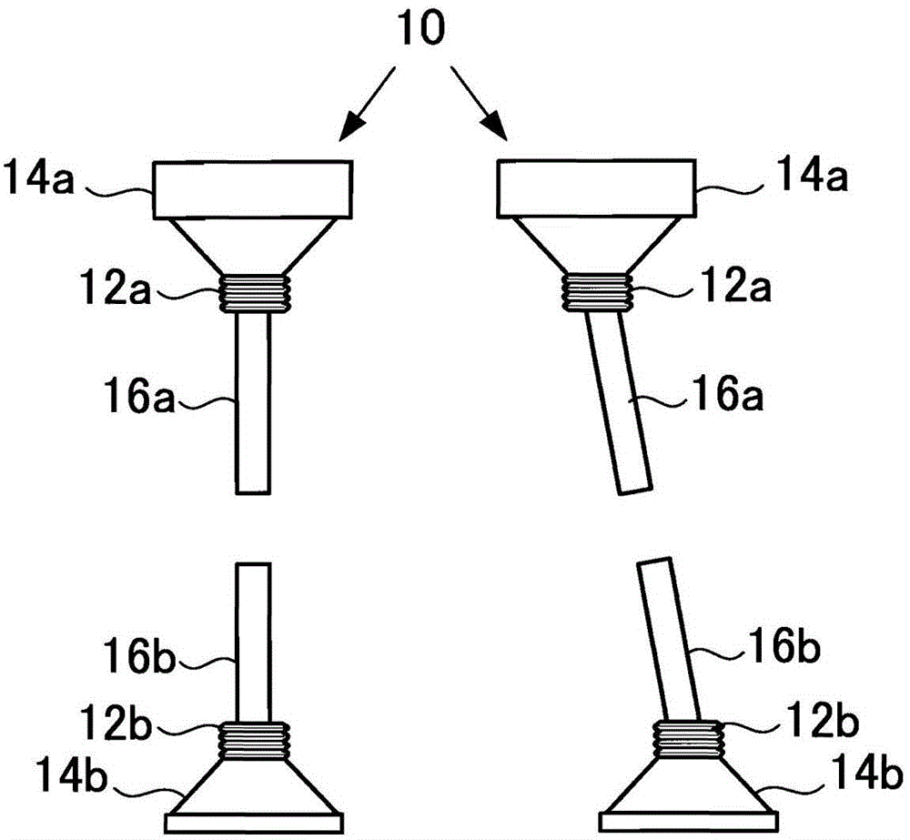
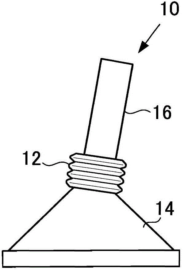
[0031] FIG. 1 is a diagram showing the shape of a nozzle according to the present embodiment, Figure 1A is the overall graph, Figure 1B It is an enlarged view of the vicinity of the bellows. In the figure, reference numeral 10 is a nozzle, and as components constituting the nozzle 10, reference numeral 14a is an upper holding portion, reference numeral 14b is a lower holding portion, reference numeral 16a is an upper machining fluid ejection portion, and reference numeral 14a is an upper holding portion. 16b is a lower machining fluid discharge part. Each holding portion 14 has a conical shape, and each machining fluid discharge portion 16 has a cylindrical shape. In addition, in terms of material, each holding portion 14 and each machining fluid discharge portion 16 are formed of ceramics or resin, but they may also be formed of metal.

[0032] In addition, reference numerals 12 a and 12 b denote rubber bellows that connect the respective holding portions 14 and the mach...

no. 2 approach

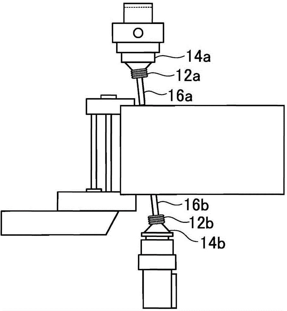
[0037] image 3 It is a figure showing the shape of the machining fluid discharge part of this embodiment. The difference from the first embodiment is that, instead of the bellows 12 of the first embodiment, a metal spherical part 18 is provided at the end of the machining fluid discharge part 16 as the angle changing member, and a metal spherical part 18 is provided at the end of the holding part 14. A bearing portion 19 is provided, and the spherical portion 18 is fitted into the bearing portion 19 . Both the spherical body portion 18 and the bearing portion 19 in this embodiment are formed of metal.

[0038] In this embodiment, compared with the structure of the bellows 12 of the first embodiment, the machining fluid ejection part 16 can be more smoothly moved in the U-axis direction by the spherical bearing structure composed of the spherical part 18 and the bearing part 19. , Tilting in the direction of the V axis.

[0039] In addition, both the structure of the bellow...


PUM


Abstract

A processing liquid ejection device of a wire electrical discharge machine includes: a processing liquid ejection portion (16); a holding portion (14) of which the diameter decreases as the holding portion (14) approaches the processing liquid ejection portion (16); and an angle changing member (12) that is provided in a connection portion between the processing liquid ejection portion and the holding portion so as to change the relative angle between the processing liquid ejection portion and the holding portion.

Description

technical field [0001] The present invention relates to a machining fluid ejection device for a wire electric discharge machine. Background technique [0002] In a wire electrical discharge machine, a voltage is applied between the wire electrode and the workpiece to generate electric discharge, and at the same time, the relative position between the wire electrode and the workpiece is changed, and the workpiece is machined into a desired shape. In addition, during machining, the machining fluid from the nozzle is ejected to the discharge site. [0003] The machining fluid discharged to the discharge site circulates through the machining fluid circulation path formed between the machining fluid tank. Furthermore, in the machining fluid circulation path, washing and cooling of the machining fluid are performed. [0004] The processing speed of the wire electrical discharge machine is usually relatively slow compared with other machine tools. As one of the methods for incre...

Claims


Application Information

Patent Timeline
Patent Type & Authority Applications(China)
IPC IPC(8): B23H7/02B23H11/00
CPCB23H7/101
Inventor 山冈正英
Owner FANUC LTD
Learn More