
A double-head cutting machine for electronic components

A technology of electronic components and cutting machine, which is applied in the field of double-head cutting machines for electronic components processing, and can solve the problems of slow cutting speed, inaccurate cutting and slow processing speed, etc.

Active Publication Date: 2019-06-07
广东超导电子有限公司
View PDF6 Cites 0 Cited by
  • Summary
  • Abstract
  • Description
  • Claims
  • Application Information

AI Technical Summary

Problems solved by technology

[0003] Cutting machine is a device for cutting redundant aluminum wires of electronic components. Nowadays, many electronic components such as resistors have aluminum wires at both ends. In order to better connect to the circuit board, it is necessary to cut the aluminum wires on both sides For cutting, most of today's cutting equipment is unilateral. For electronic components that need to be cut on both sides, there are disadvantages of slow cutting speed, inaccurate cutting, and slow processing speed. Therefore, it is urgent to develop a cutting High-efficiency, double-head cutting machine for electronic component processing that can accurately cut both sides

Method used


Image

  • A double-head cutting machine for electronic components
  • A double-head cutting machine for electronic components
  • A double-head cutting machine for electronic components

Examples


Embodiment 1

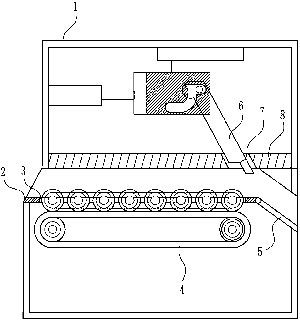
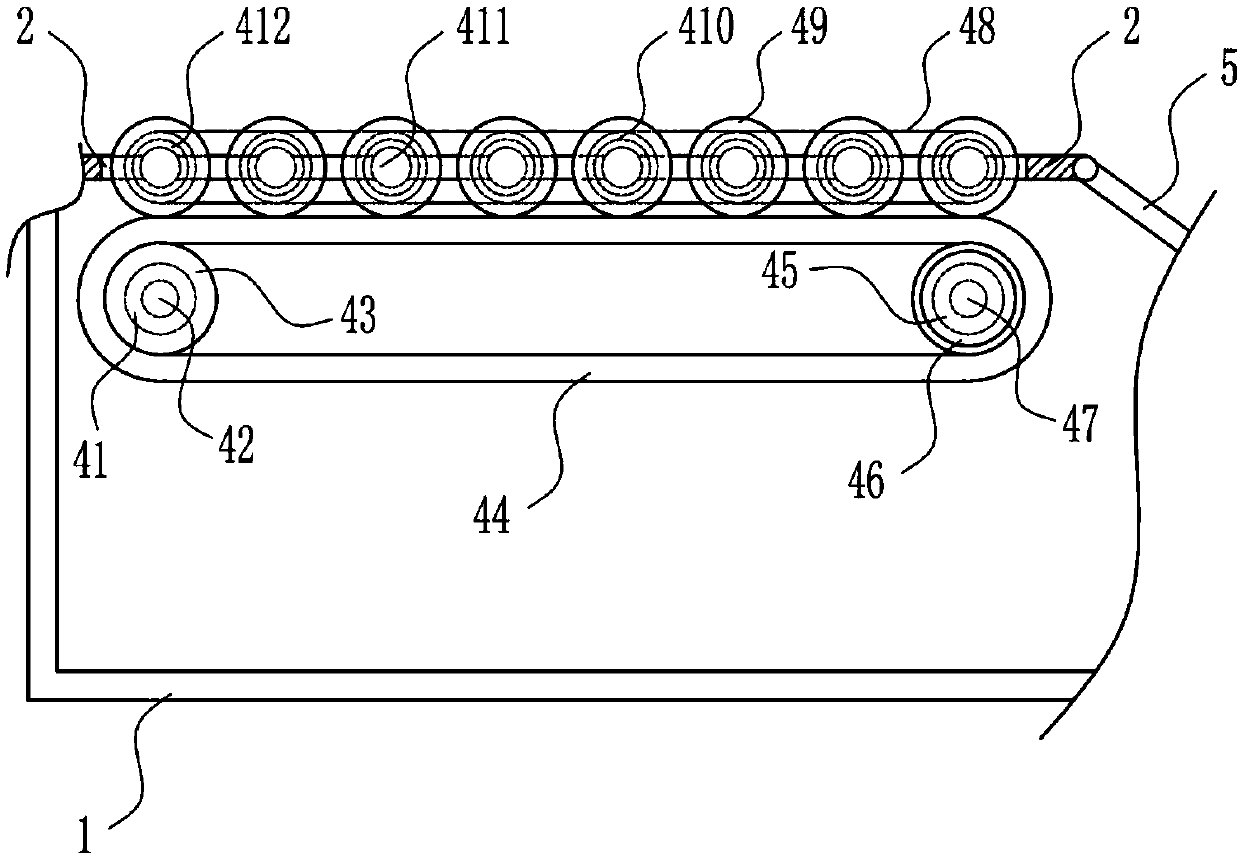
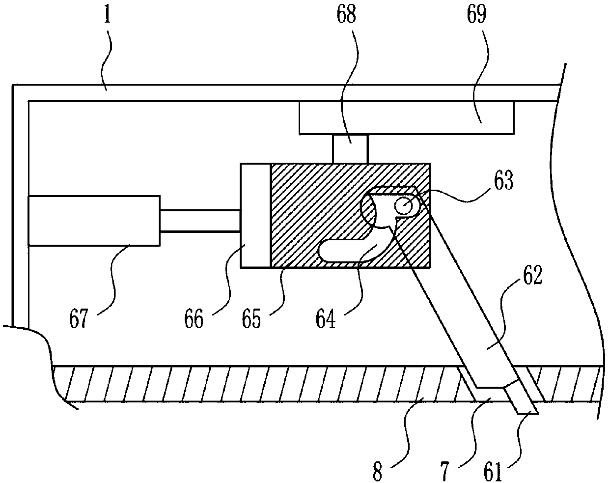
[0033] A double-head cutting machine for processing electronic components, such as Figure 1-7 As shown, it includes a working box 1, a conveying trough 2, a conveying device 4, an outlet trough 5, a cutting device 6, and a horizontal plate 8. The working box 1 is connected with a horizontal plate 8 front and back, and a conveying trough is arranged on the left side of the bottom of the horizontal plate 8. 2. The transfer slot 2 communicates with the left wall of the working box 1. The bottom of the transfer slot 2 is provided with a bar-shaped hole 3. The right side of the horizontal plate 8 is provided with an export slot 5. The export slot 5 communicates with the right wall of the working box 1. The horizontal plate 8 is set on the right side. The top of the working box 1 is provided with a cutting device 6, the cutting device 6 passes through the guiding hole 7, and the lower part of the working box 1 is provided with a conveying device 4, and the conveying device 4 is conn...

Embodiment 2

[0035] A double-head cutting machine for processing electronic components, such as Figure 1-7 As shown, it includes a working box 1, a conveying trough 2, a conveying device 4, an outlet trough 5, a cutting device 6, and a horizontal plate 8. The working box 1 is connected with a horizontal plate 8 front and back, and a conveying trough is arranged on the left side of the bottom of the horizontal plate 8. 2. The transfer slot 2 communicates with the left wall of the working box 1. The bottom of the transfer slot 2 is provided with a bar-shaped hole 3. The right side of the horizontal plate 8 is provided with an export slot 5. The export slot 5 communicates with the right wall of the working box 1. The horizontal plate 8 is set on the right side. The top of the working box 1 is provided with a cutting device 6, the cutting device 6 passes through the guiding hole 7, and the lower part of the working box 1 is provided with a conveying device 4, and the conveying device 4 is conn...

Embodiment 3

[0038] A double-head cutting machine for processing electronic components, such as Figure 1-7 As shown, it includes a working box 1, a conveying trough 2, a conveying device 4, an outlet trough 5, a cutting device 6, and a horizontal plate 8. The working box 1 is connected with a horizontal plate 8 front and back, and a conveying trough is arranged on the left side of the bottom of the horizontal plate 8. 2. The transfer slot 2 communicates with the left wall of the working box 1. The bottom of the transfer slot 2 is provided with a bar-shaped hole 3. The right side of the horizontal plate 8 is provided with an export slot 5. The export slot 5 communicates with the right wall of the working box 1. The horizontal plate 8 is set on the right side. The top of the working box 1 is provided with a cutting device 6, the cutting device 6 passes through the guiding hole 7, and the lower part of the working box 1 is provided with a conveying device 4, and the conveying device 4 is conn...


PUM


Abstract

The invention relates to a foot cutting machine, and particularly relates to a double-head foot cutting machine for processing of an electronic element. The double-head foot cutting machine for the processing of the electronic element is efficient to cut feet and capable of accurately synchronously cutting the feet from two edges. The machine comprises a work box, etc., wherein a transverse plateis connected into the work box in the front-back direction; a conveying box which communicates with the left side of the work box is formed in the bottom left side of the transverse plate; a stripy hole is formed in the bottom part of the conveying groove; an exporting groove which communicates with the right wall of the work box is formed in the right side of the transverse plate; a guide hole isformed in the right part of the transverse plate; a cutting device is arranged on the top part of the work box and passes through the guide hole; a conveying device is arranged at the inner lower part of the work box. According to the machine, the problems of slow foot cutting, inaccurate foot cutting and slow processing can be solved; two cutting blades in a cutting device are utilized for cutting from front and back, so that the processing is quickly performed.

Description

technical field [0001] The invention relates to a cutting machine, in particular to a double-head cutting machine for processing electronic components. Background technique [0002] Electronic components are components of electronic components and small electrical machines and instruments. They are often composed of several parts and can be used in similar products; they often refer to certain parts in industries such as electrical appliances, radios, and instruments, such as capacitors, transistors, The general term for hairsprings, springs and other sub-devices. Common ones include diodes, etc. Electronic components include: resistors, capacitors, potentiometers, electron tubes, radiators, electromechanical components, connectors, semiconductor discrete devices, electroacoustic devices, laser devices, electronic display devices, optoelectronic devices, sensors, power supplies, switches, micro-motors, Electronic transformers, relays, printed circuit boards, integrated cir...

Claims


Application Information

Patent Timeline
Patent Type & Authority Patents(China)
IPC IPC(8): B21F11/00B21F23/00
CPCB21F11/00B21F23/00
Inventor 吴浪黄咪熊杰
Owner 广东超导电子有限公司
Learn More