Biological vaccine inactivation device and control method

A control method and vaccine technology, applied in water supply devices, sanitary equipment for toilets, heating, etc., can solve the problems of inability to guarantee animal safety, low automation level, and low inactivation efficiency, and achieve improved vaccine inactivation efficiency, The effect of a high level of automation

Active Publication Date: 2015-07-29
北京科嘉德技术有限公司
View PDF4 Cites 1 Cited by
  • Summary
  • Abstract
  • Description
  • Claims
  • Application Information

AI Technical Summary

Problems solved by technology

Chemical inactivation mainly uses chemical reagents to inactivate vaccines. The amount of chemical reagents used has a great impact on the inactivation efficiency, but it is difficult to control the amount of chemical reagents used. In addition, after the vaccine is inactivated, there are still residues in the vaccine. Chemical reagents will not only affect the quality of the vaccine, but also the use of biological vaccines with chemical reagent residues cannot guarantee the safety of animals; physical inactivation includes methods such as heat sterilization and ultrasonic cracking of cells. Physical methods are relatively safe, especially the heat sterilization method is a large The method commonly used by most vaccine manufacturers is to maintain the temperature required for vaccine inactivation by providing water at the temperature required for inactivation to the jacket of the vaccine inactivation tank. However, this method of vaccine inactivation is currently mostly manual. Low efficiency and low level of automation

Method used


Image

  • Biological vaccine inactivation device and control method
  • Biological vaccine inactivation device and control method

Examples


Embodiment Construction

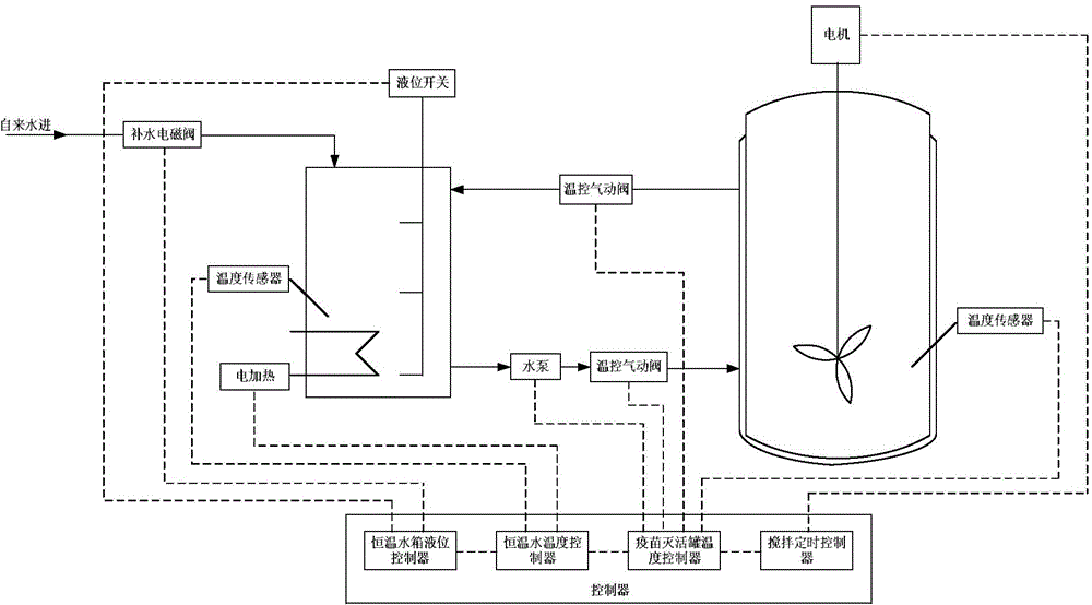
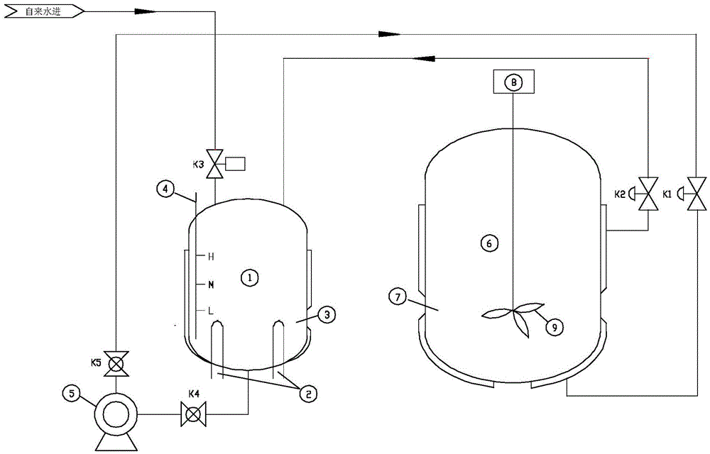
[0015] The specific embodiments of the present invention will be further described below in conjunction with the accompanying drawings.

[0016] Put the vaccine to be inactivated into the inactivation tank, open the hand valves K4 and K5, and perform the following procedures:

[0017] (1) Collect the liquid level signal of the constant temperature water tank to control the liquid level of the constant temperature water tank:

[0018] 1) When the liquid level of the constant temperature water tank is "low", the electric heating 2 heating and the operation of the water pump 5 are prohibited (for protection), and the water replenishment solenoid valve K3 is turned on to replenish water for the constant temperature water tank.

[0019] 2) When the liquid level of the constant temperature water tank is "medium", the prohibition on the electric heating 2 and the water pump 5 is lifted; the replenishment solenoid valve K3 remains open, and continues to replenish water for the constan...


PUM


Abstract

The invention belongs to the field of pharmaceutical production and particularly relates to a biological vaccine inactivation device and a control method. The biological vaccine inactivation device comprises a thermostatic water tank, a vaccine inactivation tank and controllers, wherein the thermostatic water tank is equipped with a temperature sensor, a three-point liquid level sensor and electric heating tubes, as well as a water replenishing solenoid valve; the vaccine inactivation tank is equipped with a stirring motor, stirring paddles and a temperature sensor, and a heat-insulating jacket is arranged outside the vaccine inactivation tank; a thermostatic water pump, temperature-controlled pneumatic valves and hand-operated valves are assembled between the thermostatic water tank and the vaccine inactivation tank; the controllers consist of a thermostatic water tank level controller, a thermostatic water temperature controller, a vaccine inactivation tank temperature controller and a stirring timing controller; the thermostatic water tank is used for providing a constant-temperature water source required for inactivation; the vaccine inactivation tank temperature controller is used for measuring the temperature of the vaccine inactivation tank to control the thermostatic water pump and the temperature-controlled pneumatic valves to start or stop to pump thermostatic water into the jacket of the vaccine inactivation tank so as to keep the temperature of the vaccine inactivation tank constant. The biological vaccine inactivation device and the control method can improve the biological vaccine inactivation efficiency.

Description

technical field [0001] The invention relates to a biological vaccine inactivation device and belongs to the field of pharmaceutical production. Background technique [0002] Biological vaccine is a special drug, as a biological product produced by the joint development of immunological experience theory and biotechnology, it eliminates the threat of many infectious diseases to animal life from the perspective of preventive measures, and promotes the healthy development of the breeding industry , to ensure people's health. Inactivated vaccines are treated with materials containing bacteria or viruses using physical or chemical methods to make them lose infectivity and toxicity while maintaining immunogenicity, combined with corresponding adjuvants, can produce automatic immunity after inoculation to animals, and prevent diseases A class of biological products. [0003] With the rapid development of animal husbandry, the demand for biological vaccines is increasing year by y...

Claims


Application Information

Patent Timeline
IPC IPC(8): A61L2/24A61L2/04
Inventor 潘丰刘艳
Owner 北京科嘉德技术有限公司
Why Eureka
Try Eureka