
Sampling rate conversion device and sampling rate conversion method with bandwidth being continuously variable

A conversion device and sampling rate technology, which is applied in the field of sampling rate conversion devices, can solve problems such as poor flexibility, large hardware system consumption, and high hardware resource occupancy rate

Active Publication Date: 2015-07-22
成都国恒空间技术工程股份有限公司
View PDF4 Cites 30 Cited by
  • Summary
  • Abstract
  • Description
  • Claims
  • Application Information

AI Technical Summary

Problems solved by technology

[0003] Chinese Patent No. 200810057286.1 discloses a method and device for implementing a digital baseband variable rate conversion modulation system. For signals with different symbol rates, different channel selection methods are used to achieve a fixed sampling rate output. However, the device with this structure is only applicable to It is used when the symbol rate is low, and can only realize integer multiple sampling rate conversion. If the symbol rate is to be increased, the number of channels for sampling rate conversion needs to be increased. The hardware resource occupancy rate of the device is high, and the flexibility is poor. High consumption of hardware system

Method used


Image

  • Sampling rate conversion device and sampling rate conversion method with bandwidth being continuously variable
  • Sampling rate conversion device and sampling rate conversion method with bandwidth being continuously variable
  • Sampling rate conversion device and sampling rate conversion method with bandwidth being continuously variable

Examples


Embodiment Construction

[0047] The technical solution of the present invention will be further described in detail below in conjunction with the accompanying drawings, but the protection scope of the present invention is not limited to the following description.

[0048] Such as figure 1 As shown, a sampling rate conversion device with continuously variable bandwidth is composed of an up-sampling rate conversion unit and a down-sampling rate conversion unit.

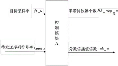
[0049] The up-sampling rate conversion unit includes a shaping filter, an integer multiple interpolation module A, a fractional multiple interpolation module A, a DAC digital-to-analog converter, and a control module A. The shaping filter is used to receive the sequence that the sending end needs to send, and M times the fixed multiple of times to perform interpolation filtering processing on the sequence to be sent, to complete the spectrum shaping of the sequence to be sent, M is generally taken as 4, the root-raised cosine filter can be sele...


PUM


Abstract

The invention discloses a sampling rate conversion device and a sampling rate conversion method with the bandwidth being continuously variable. The sampling rate conversion device comprises an upper sampling rate conversion unit and a lower sampling rate conversion unit, wherein the upper sampling rate conversion unit comprises a shaping filter, an integral multiple interpolation module A, a fractional multiple interpolation module A, a DAC (digital-to-analog converter) and a control module A, the shaping filter receives a sequence to be sent, and the sequence to be sent is sequentially processed by the integral multiple interpolation module A, the fractional multiple interpolation module A and the DAC and then outputted, the lower sampling rate conversion unit comprises an ADC (analog-to-digital converter), a fractional multiple interpolation module B, an integral multiple extraction module B, a matched filter and a control module B, signals of a receiving end are inputted into the ADC, the signals are sequentially processed by the fractional multiple interpolation module B, the integral multiple extraction module B and the matched filter and then outputted, and the control module controls the integral multiple interpolation times, the integral multiple extraction times and the fractional multiple interpolation times. According to the invention, the hardware resource occupation rate is low, the number of half-band filters can be increased or decreased according to a relation between a target sampling rate and an input signal symbol rate, thereby adapting to sampling rate conversion processing of any signals with the bandwidth being variable.

Description

technical field [0001] The invention relates to the fields of wireless communication and digital signal processing, in particular to a sampling rate conversion device and method with continuously variable bandwidth. Background technique [0002] Software Definition Radio (SDR, Software Definition Radio) has always been a research hotspot in the field of digital signal processing. Its basic idea is to make the digital processing unit as close as possible to the RF front-end and reduce the signal processing area in the analog domain, so as to realize multi-band, multi-user, and multi-mode data processing on the same hardware design platform. With the rapid development of wireless communication technology, a variety of protocols and systems have been continuously proposed, and it is particularly urgent to design a general-purpose software radio platform that can be compatible with different rates and bandwidths. In the software radio system, if the radio frequency end is compa...

Claims


Application Information

Patent Timeline
IPC IPC(8): H03M1/66H03H17/00
Inventor 邹刚冯佳梅
Owner 成都国恒空间技术工程股份有限公司
Learn More