Eureka AIR delivers breakthrough ideas for toughest innovation challenges, trusted by R&D personnel around the world.

Side-in display module and display device

A display module and side-entry technology, which is applied to lighting devices, fixed lighting devices, components of lighting devices, etc., can solve problems such as complicated assembly procedures

Active Publication Date: 2015-07-22
HISENSE VISUAL TECH CO LTD
View PDF8 Cites 10 Cited by
  • Summary
  • Abstract
  • Description
  • Claims
  • Application Information

AI Technical Summary

Problems solved by technology

[0004] The inventors found that in order to achieve the above effects, the technicians added a quantum dot diaphragm to the existing module, which would inevitably lead to complicating the assembly procedure

Method used


Image

  • Side-in display module and display device
  • Side-in display module and display device
  • Side-in display module and display device

Examples


Embodiment 1

[0023] Such as image 3 and Figure 4 As shown, the present invention provides a side-entry display module, including a backplane 21, an excitation light source 22, a reflector 23, an optical film 25, a plastic frame 26 and a liquid crystal panel 27, and also includes: a light guide plate 241, a coating The refraction layer 242 disposed on the light guide plate 241 , and the quantum dot layer 243 coated on the refraction layer 242 . In this embodiment, the back plate 21 is a rigid component used to support the structure of the entire side-entry display module. There is an upward folded edge around the back plate 21, which is used to fix the plastic frame and excite The light source 22 forms a limited space for accommodating the reflective sheet 23, the light guide plate 241 and the like.

[0024] The light incident surface of the light guide plate 241 is set relative to the excitation light source 22, and is used to receive the light emitted by the excitation light source. A...

Embodiment 2

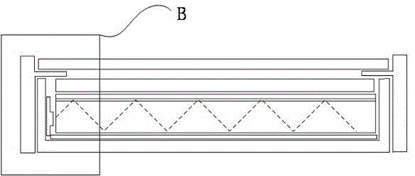
[0034] Such as Figure 5 and Figure 6 As shown, the present invention provides a side-entry display module, which includes an excitation light source 31, an optical film 33, a plastic frame 34 and a liquid crystal panel 35, and also includes a light guide plate 321 and a refraction layer coated on the light guide plate 321. 322 . The quantum dot layer 323 coated on the refraction layer 322 , preferably, further includes a reflective layer 324 disposed on the other side of the light guide plate opposite to the refraction layer 322 . In this embodiment, the light guide plate 321 is a rigid component used to support the structure of the entire side-entry display module. The limit of panel 35.

[0035] The light incident surface of the light guide plate 321 is set relative to the excitation light source 31, and is used to receive the light emitted by the excitation light source. A reflective layer 324 is arranged under the light guide plate 321. The light is reflected to the i...


PUM


Abstract

The embodiment of the invention discloses a side-in display module and a display device. The side-in display module comprises a light guide plate, a refraction layer and a quantum dot layer. The light emitting face of the light guide plate is coated with the refraction layer, the surface of the refraction layer is coated with the quantum dot layer, the quantum dot layer and the light guide plate are combined into an integrated component, and the assembling procedure is simplified. Due to the fact that the refractive index of the quantum dot layer is similar to that of the light guide plate, a full-reflection light path in the light guide plate will be damaged if the light guide plate is directly coated with the quantum dot layer, and the side-in display module can not display information normally, the refractive index of the refraction layer arranged between the light guide plate and the quantum dot layer in a coating mode is smaller than that of the light guide plate. The refraction layer with the refraction index smaller than that of the light guide plate is arranged between the light guide plate and the quantum dot layer in the coating mode, so that on the basis that the normal display function of the side-in display module is achieved, the assembling procedure of the side-in display module is simplified.

Description

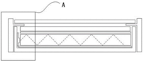
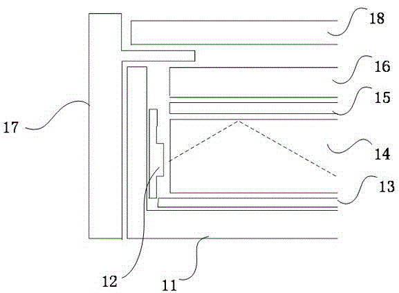
technical field [0001] The invention relates to the field of display technology, in particular to a side-entry display module and a display device. Background technique [0002] Nowadays, LCD TVs have entered more and more families. With the advancement of technology, LCD TVs have met many needs of people in many technical fields. The standard of color display is also gradually improved. In order to realize the high color gamut of the display device, in the prior art, the backlight supply of the LCD TV is realized by using the mechanism of exciting the quantum dots by the excitation light source. [0003] In the prior art, the side-entry display modules using the quantum dot mechanism are as follows: figure 1 and figure 2 As shown: it includes a backplane 11 , an excitation light source 12 , a reflection sheet 13 , a light guide plate 14 , a quantum dot film 15 , an optical film 16 , a plastic frame 17 and a liquid crystal panel 18 . The light guide plate 14 can receive...

Claims


Application Information

Patent Timeline
IPC IPC(8): F21S8/00F21V13/12G02F1/13357F21Y101/02
Inventor 李富琳乔明胜宋志成
Owner HISENSE VISUAL TECH CO LTD
Why Eureka
Eureka Blog
Learn More