
Heavy duty type high-temperature conveying chain

A conveying chain, high temperature technology, applied in the field of heavy-duty high-temperature conveying chain, can solve the problems of reduced strength, chain wear resistance and tensile strength, unsuitable for tensile strength, etc., to achieve the effect of good carrying capacity

Inactive Publication Date: 2015-07-22
YIDU ZHONGQI HEAVY IND MASCH CO LTD
View PDF6 Cites 0 Cited by
  • Summary
  • Abstract
  • Description
  • Claims
  • Application Information

AI Technical Summary

Problems solved by technology

When the chain plate clamping the roller chain is installed on the secondary attachment plate, since the primary attachment is made of the chain plate itself, the chain must be installed on the bottom or both sides of the secondary attachment (tray or hopper). During high-temperature transportation, the rollers and chain plates are subjected to heat radiation and heat conduction at the same time, resulting in a decrease in strength as the temperature rises, serious wear of the rollers, and even easy to be stuck.
[0004] The second type is the round link chain that has also been used as a national standard. It is composed of a single closed long ring connected in staggered series at 90°. The attachment is fixed by a special connecting ring to complete the scraping or lifting task. The scraping and pushing Form, the chain is basically buried in the material, so that when the temperature of the material reaches a certain height, the wear resistance and tensile strength of the chain will be greatly reduced
This type of chain is limited by the diameter of the spiral steel wire, so it should not be large enough to meet sufficient tensile strength, and the tray fixed on it should not be thick or large to meet the large volume and high temperature materials. Require

Method used


Image

  • Heavy duty type high-temperature conveying chain
  • Heavy duty type high-temperature conveying chain
  • Heavy duty type high-temperature conveying chain

Examples


Embodiment Construction

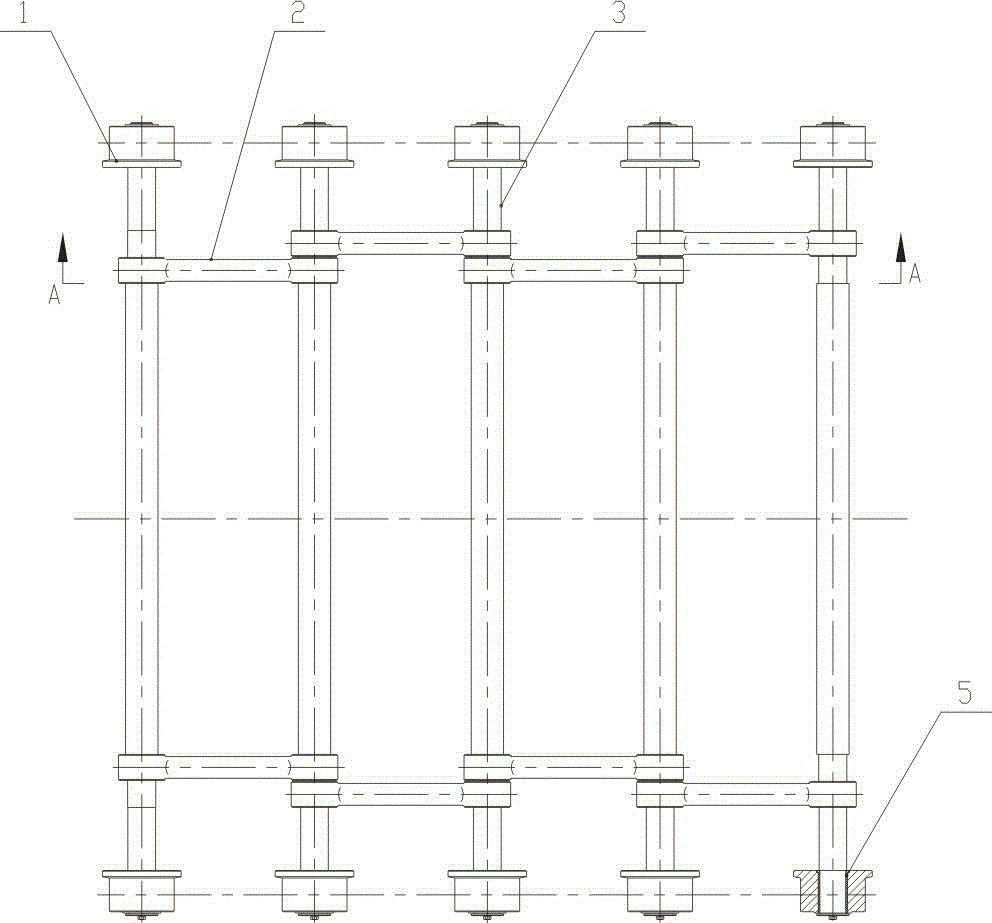
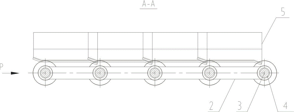
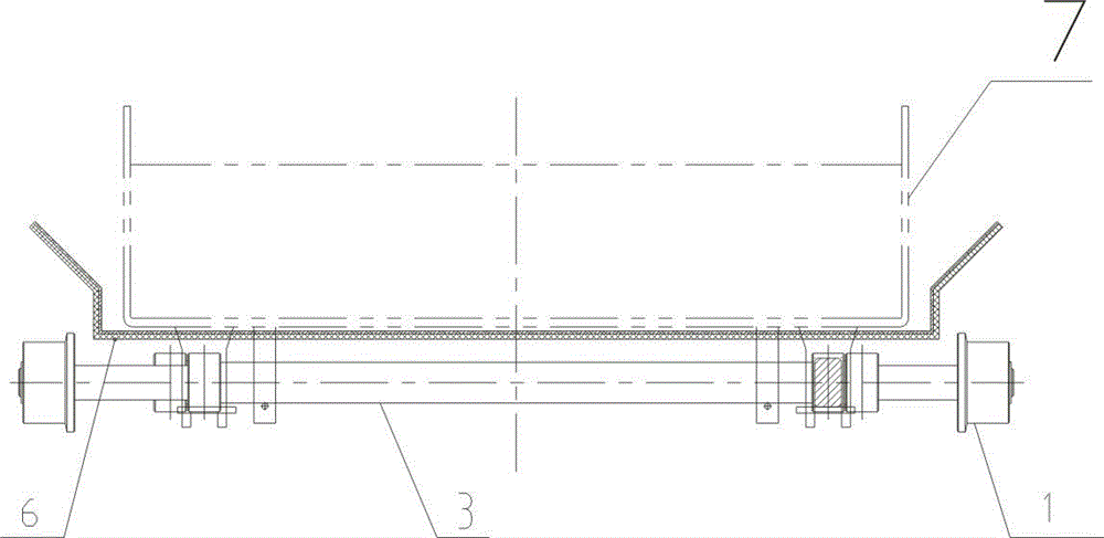
[0026] like Figure 1~Figure 3 As shown, a heavy-duty high-temperature conveyor chain includes left and right rows of chain rods, the left and right rows of chain rods are connected in series through the through shaft 3 to form a well-shaped grid, and the chain rod 2 and the through shaft 3 pass through the self-lubricating bearing bush 4 Hinged, the bearing roller 1 is assembled with the through shaft 3 through the sliding bearing 5, and the well-shaped grid is equipped with a heat-insulating reflective layer 6. A certain distance is formed between the bearing roller 1 and the chain rod 2 through the shaft extension of the through shaft 3 , which is used to extend the heat conduction path of the bearing roller 1 . The chain rod 2 is shaped by die forging.

[0027] exist figure 1 In the general assembly drawing, the carrying roller 1 and the chain rod 2 form a certain distance through the axial extension of the through shaft 3 to extend the heat conduction path of the carryi...


PUM


Abstract

A heavy duty type high-temperature conveying chain comprises a left row of chain bars and a right row of chain bars, the left row of chain bars and the right row of chain bars are connected in series by means of through shafts so as to form a grid shaped like the Chinese character 'jing', each chain bar is hinged to the corresponding through shaft through a self-lubricating bearing pad, each bearing sliding wheel is assembled on the corresponding through shaft through a sliding bearing, and a thermal insulation reflecting layer is installed on the grid shaped like the Chinese character 'jing'. The heavy duty type high-temperature conveying chain integrates the advantages of a bush roller chain, the advantages of a die-forged chain and the advantages of a mesh belt, is suitable for supporting trays or pans or hoppers or compartments containing high-temperature materials, and completes conveying tasks. The heavy duty type high-temperature conveying chain has the advantages that high temperature resistance is achieved, the conveying quantity is large, and secondary accessories are connected firmly and dismounted conveniently.

Description

technical field [0001] The invention relates to a heavy-duty high-temperature conveying chain, which is used for conveying high-temperature materials in a high-temperature environment. Background technique [0002] At present, there are roughly four types of traction parts as key components in the field of warm transportation: [0003] The first type is the sleeve roller chain (plate chain) which has already formed the national standard. It is mainly composed of inner and outer chain plates, pin shafts, sleeves and rollers. Occasionally, the sleeves are canceled and the rollers are directly assembled on the pin shafts. Basically, the inner and outer chain plates are deformed into primary attachments to support or pull materials, and bulk materials are equipped with secondary attachments (trays or hoppers) to lift or scrape and push in the groove to complete the conveying task. Due to the cooperation and sliding friction between the various parts, it is inconvenient to direc...

Claims


Application Information

Patent Timeline
Patent Type & Authority Applications(China)
IPC IPC(8): B65G17/40
CPCB65G17/40
Inventor 王海涛
Owner YIDU ZHONGQI HEAVY IND MASCH CO LTD
Learn More