
Annular deep and narrow groove turning tool

A turning tool and narrow groove technology, which is applied in the direction of lathe tools, turning equipment, cutting blades, etc., can solve the problems that the size and shape accuracy of the groove cannot meet the technical requirements, and chip removal is difficult, so as to achieve simple structure and easy processing. The effect of low cost and low price

Inactive Publication Date: 2015-07-22
HENGYANG FENGSHUN AXLE CO LTD
View PDF0 Cites 4 Cited by
  • Summary
  • Abstract
  • Description
  • Claims
  • Application Information

AI Technical Summary

Problems solved by technology

[0002] The existing motor coupling shaft or the connection sleeve between the antenna and the feeder often needs an unconventional echo groove to eliminate external interference. The depth of this annular groove is usually more than 10 times the groove width. , using conventional turning tools, chip removal is very difficult, and the size and shape accuracy of the groove are difficult to meet the technical requirements

Method used


Image

  • Annular deep and narrow groove turning tool
  • Annular deep and narrow groove turning tool
  • Annular deep and narrow groove turning tool

Examples


Embodiment Construction

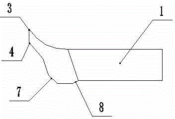
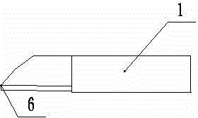
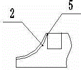
[0016] As shown in the attached figure: a ring-shaped deep and narrow groove turning tool, which is divided into rough turning tool and fine turning tool, wherein both the rough turning tool and the finishing turning tool include: tool handle 1, cutter head arc 2, cutter head front Angle 3, cutter head rear angle 4, cutter head auxiliary rear angle 5, cutter head auxiliary deflection angle 6, front chamfer 7, rear chamfer 8, tool handle 1 is set on the left side of the turning tool, and tool head arc 2 is set on At the front of the turning tool, the rake angle 3 of the tool head is located at the tip of the arc 2 of the tool head; , the cutter head secondary angle 6 is located below the cutter head back angle 4, the front chamfer is set at the front end below the cutter head arc, the rear chamfer is set at the rear end of the front chamfer cutter head arc 2, and the cutter head rake angle 3. The cutter head rear angle 4, the cutter head auxiliary relief angle 5, the cutter hea...


PUM

PropertyMeasurementUnit
Heightaaaaaaaaaa
Central angleaaaaaaaaaa

Abstract

An annular deep and narrow groove turning tool comprises a rough turning tool body and a finish turning tool body. The rough turning tool body and the finish turning tool body both comprise a tool handle, a tool bit arc, a tool bit front angle, a tool bit rear angle, a tool bit auxiliary rear angle, a tool bit auxiliary deflection angle, a front chamfer and a rear chamber, wherein the tool handles are arranged on the left sides of the turning tool bodies, the tool bit arcs are arranged on the forefronts of the turning tool bodies, the tool bit front angles are located at the most pointed ends of the arcs, the tool bit rear angles are located at the rear ends of the tool bit front angles, the tool bit auxiliary rear angles are located at the upper ends of the tool bit arcs, the tool bit auxiliary deflection angles are located below the tool bit rear angles, the front chambers are arranged at the lower ends of the tool bit arcs, the rear chamfers are arranged at the rear ends of the front chamfers, the tool bit arcs, the tool bit front angles, the tool bit rear angles, the tool bit auxiliary rear angles, the tool bit auxiliary deflection angles, the front chambers and the rear chambers form tool bit assemblies, and then the tool bit assemblies and the tool handles are welded and combined into a whole. By means of the annular deep and narrow groove turning tool, it can be guaranteed that the machining size is stable, the surface roughness is effectively improved, and the annular deep and narrow groove turning tool is simple in structure, low in machining cost and low in price.

Description

technical field [0001] The invention relates to a tool in the field of mechanical processing, in particular to a ring-shaped deep narrow groove turning tool. Background technique [0002] The existing motor coupling shaft or the connection sleeve between the antenna and the feeder often needs an unconventional echo groove to eliminate external interference. The depth of this annular groove is usually more than 10 times the groove width. , using conventional turning tools, chip removal is very difficult, and the size and shape accuracy of the groove are difficult to meet the technical requirements. Contents of the invention [0003] The purpose of the present invention is to overcome the above-mentioned shortcomings of the prior art and provide a ring-shaped deep and narrow groove turning tool, which can ensure stable processing dimensions, effectively improve surface roughness, and has simple structure, low processing cost and low price. [0004] The technical scheme ...

Claims


Application Information

Patent Timeline
IPC IPC(8): B23B27/00
CPCB23B27/00B23B2200/28B23B2222/84
Inventor 刘登发
Owner HENGYANG FENGSHUN AXLE CO LTD
Learn More