Protein production accelerator
一种闪烁体、闪烁体层的技术,应用在摄影工艺、X射线/红外工艺、仪器等方向,能够解决发光不均、X射线荧光体体积变小、空间变窄等问题
- Summary
- Abstract
- Description
- Claims
- Application Information
AI Technical Summary
Problems solved by technology
Method used
Image
Examples
Embodiment 1)
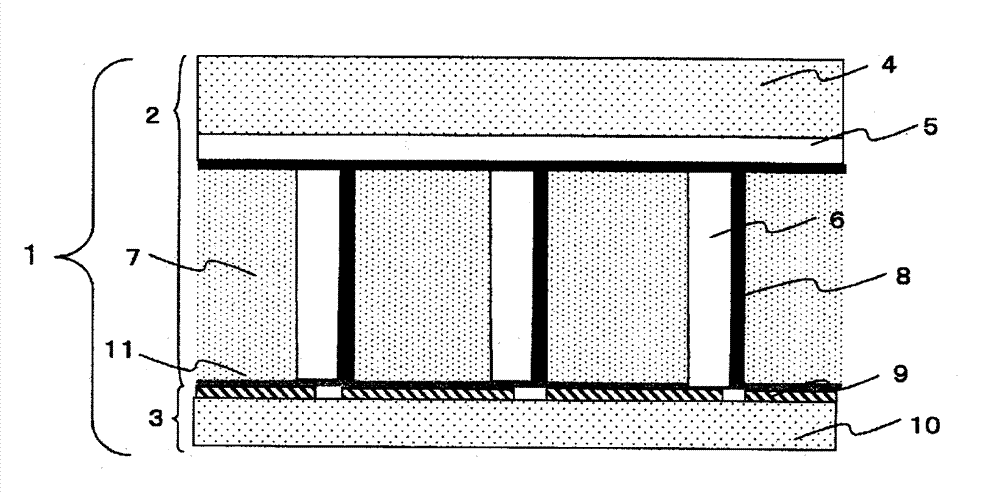
[0140] On a glass substrate (AGC Asahi Glass Co., Ltd.; AN-100) of 500mm×500mm×thickness 0.5mm, the above-mentioned base paste was coated with a 15μm bar coater, dried at 150°C for 30 minutes, and heat-cured. A base paste film with a thickness of 12 μm was formed. Next, the photosensitive paste for partition walls was coated with a die coater so as to have a dried thickness of 500 μm, and dried at 120° C. for 30 minutes to form a photosensitive paste coating film for partition walls.
[0141] Next, through a photomask (a chrome mask having grid-like openings with a line width of 10 μm and a vertical and horizontal pitch of 125 μm) formed with openings corresponding to the desired partition rib pattern, the photomask was heated at 700 mJ / cm using an ultra-high pressure mercury lamp. 2 The exposure amount of the photosensitive paste coating film for partition walls was exposed. The exposed photosensitive paste coating film for barrier ribs was developed in 0.5% aqueous ethanola...
Embodiment 2)
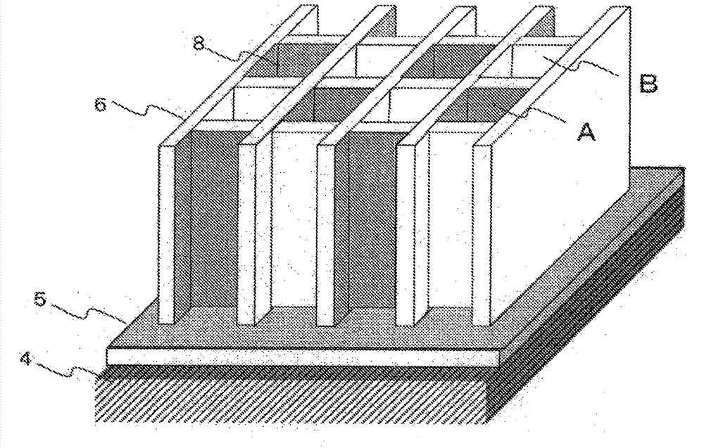
[0150] A substrate on which lattice-shaped partition walls were formed was produced by the same method as in Example 1. After apply|coating the said paste 2 for photosensitive reflection layers to the whole surface of a partition by the screen printing method, it dried at 120 degreeC for 30 minutes. Next, a mask having openings corresponding to the desired reflective layer formation pattern (both vertical and horizontal pitches are 125 μm; 125 μm square openings and light-shielding sections are alternately arranged) is arranged so that the openings coincide with the cells, Use an ultra-high pressure mercury lamp at 500mJ / cm 2 Exposure at the exposure level. The exposed photosensitive reflective layer paste coating film was developed in a 0.5% ethanolamine aqueous solution to remove unexposed portions to form a grid-like photosensitive reflective layer paste coating film pattern. Furthermore, it baked in air at 500 degreeC for 15 minutes. The result is as figure 2 As shown...
Embodiment 3)
[0153] By the same method as in Example 1, the base paste film and the photosensitive paste coating film for partition walls were formed on the glass substrate.
[0154] Next, exposure and exposure were performed under the same conditions as in Example 1 through a photomask (a photomask having stripe-shaped openings with a pitch of 125 μm and a line width of 10 μm) in which openings corresponding to the desired partition rib pattern were formed. Developed to form a striped photosensitive paste coating film pattern. Furthermore, the photosensitive paste coating film pattern was calcined in air at 595° C. for 15 minutes to produce a film having a partition wall spacing L2 of 125 μm, a top width L4 of 15 μm, a bottom width L3 of 30 μm, and a partition wall height L1 formed on the surface. A substrate with stripe-shaped partition walls of 330 μm and a size of 480 mm×480 mm. The transmittance of light having a wavelength of 550 nm at a thickness of 30 μm of the partition wall was ...
PUM
 Abstract
Description
Claims
Application Information
 - R&D
- Intellectual Property
- Life Sciences
- Materials
- Tech Scout
- Unparalleled Data Quality
- Higher Quality Content
- 60% Fewer Hallucinations
Browse by: Latest US Patents, China's latest patents, Technical Efficacy Thesaurus, Application Domain, Technology Topic, Popular Technical Reports.
© 2025 PatSnap. All rights reserved.Legal|Privacy policy|Modern Slavery Act Transparency Statement|Sitemap|About US| Contact US: help@patsnap.com


