
Frequency divider of loudspeaker box

A frequency divider and speaker technology, applied in the direction of sensors, transducer circuits, sensor components, etc., can solve problems such as damage to load impedance and resistance characteristics, sound distortion, poor reproduction sound quality, and loss of sound signals, etc., to achieve The effect of simple structure, good reproduction sound quality and less original components

Inactive Publication Date: 2015-07-15
张廷亮
View PDF8 Cites 1 Cited by
  • Summary
  • Abstract
  • Description
  • Claims
  • Application Information

AI Technical Summary

Problems solved by technology

That is to say, the more inductance is added to the frequency divider, the more power will be lost, the greater the loss of power signal, the more serious the loss of sound signal, the sound will be distorted and the reproduction quality will be worse.
In particular, the inductance L1 and capacitor C3 connected in parallel on the circuit not only waste power that should not be wasted, but also directly destroy its load impedance and resistance characteristics, making the sound even worse

Method used


Image

  • Frequency divider of loudspeaker box
  • Frequency divider of loudspeaker box
  • Frequency divider of loudspeaker box

Examples


Embodiment 1

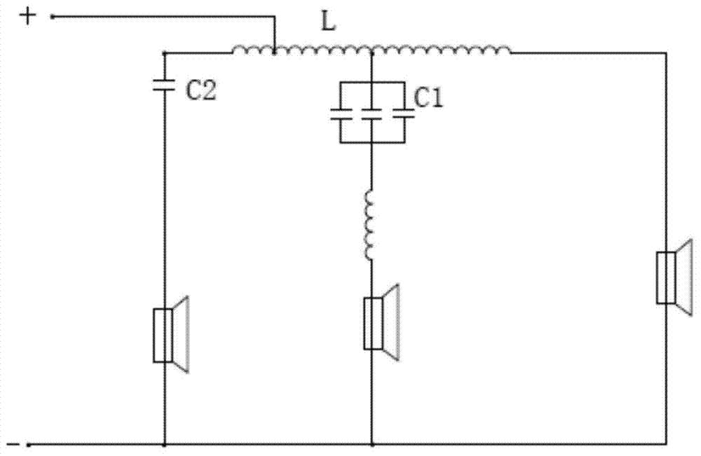
[0027] The present invention is a speaker frequency divider, the highest pitch speaker and other speakers are connected in series into the inductance coil L1. It includes an inductance coil L2, an inductance coil L1 with at least 2 taps, at least 2 capacitors C, and at least 3 speakers. The taps of the inductance coil L1 are divided into the first tap and the second tap from left to right, and the capacitor C Divided into C1, C2, ..., the speaker is divided into the first speaker, the second speaker, the third speaker, .... like figure 1 As shown, the design is divided into three frequencies, that is, high, medium and low. The input end of the circuit is connected to the first tap of the inductance coil L1, one pole of the capacitor C2 is connected to the left end of the inductance coil L1, and the other pole is connected to the first speaker. One pole of capacitor C1 is connected to the second tap, the other pole is connected to the second speaker through the inductance coil...

Embodiment 2

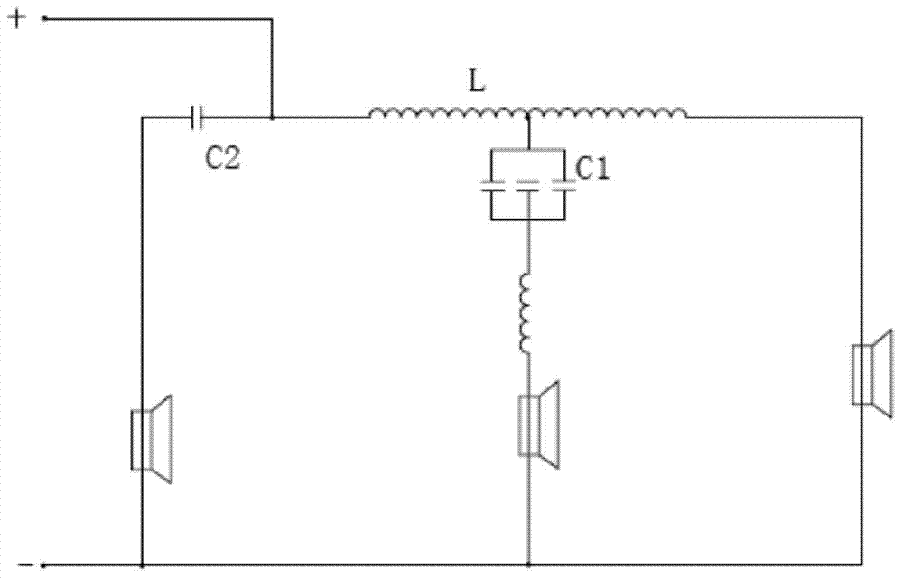
[0032] The invention relates to a speaker frequency divider, the highest pitch speaker is not connected to the inductance coil L1. It includes an inductance coil L2, an inductance coil L1 with at least one tap, at least two capacitors C, and at least three speakers. The tap of the inductance coil L1 is the first tap, ..., and the capacitor C is divided into C1, C2, ..., the speakers are divided into a first speaker, a second speaker, a third speaker, .... like image 3 As shown, the design is a three-way frequency, that is, high, medium and low. One pole of the capacitor C2 is connected to the left end of the inductance coil L1, and the other pole is connected to the first speaker. The input end of the circuit is connected between the capacitor C2 and the left end of the inductance coil L1, and one pole of the capacitor C1 is connected to the first tap. The other pole is connected to the second speaker through the inductance coil L2, the input end of the third speaker is con...


PUM


Abstract

The invention discloses a frequency divider of a loudspeaker box, which comprises an inductance coil L2, an inductance coil L1 provided with taps, capacitors C, and loudspeakers, wherein a circuit input end is connected with the first tap of the inductance coil L1; one pole of the capacitor C2 is connected with the left end head of the inductance coil L1; the other pole of the capacitor C2 is connected with the first loudspeakers; one pole of the capacitor C1 is connected with the second tap; the other pole of the capacitor C1 is connected with the second loudspeaker via the inductance coil L2; and an input end of the third loudspeaker is connected with the right end head of the inductance coil L1. According to the divider, signal input lines of the loudspeakers pass through the same inductance coil L, that is to say, the inductance coil L is reused for many times; during sound filtration, regardless of fractional frequency, input signals only pass through the single inductance coil L; all voltage of the inductance coil L is utilized almost without loss; a power signal has no loss; the distortion of sound is small; and recurrent sound quality is good.

Description

technical field [0001] The invention relates to the technical field of frequency dividers, in particular to a sound frequency divider. Background technique [0002] Speaker dividers can divide the sound signal into several frequency bands. For example, a two-way frequency divider is composed of a high-pass filter and a low-pass filter, and a three-way frequency divider adds a band-pass filter. Of course, it can also be made into a four-way frequency divider or a five-way frequency divider. The crossover is the "brain" in the speaker, which is very important to the quality of the sound. Existing speaker frequency dividers include a circuit (high-frequency frequency division circuit) connected to a tweeter, a circuit (intermediate frequency frequency division circuit) connected to a midrange speaker, and a circuit (low frequency frequency division circuit) connected to a woofer. In the circuit connected to the tweeter: let the current flow through the capacitor first, block ...

Claims


Application Information

Patent Timeline
Patent Type & Authority Applications(China)
IPC IPC(8): H04R3/00
Inventor 张廷亮
Owner 张廷亮
Learn More