
Particle sorting machine

A particle and sorting technology, which is applied in classification, solid separation, chemical instruments and methods, etc., can solve the problems that the inspection efficiency and inspection accuracy cannot be taken into account at the same time, the inspection is laborious, and the spread is messy.

Inactive Publication Date: 2015-07-15
浙江中科光铭光电股份有限公司
View PDF9 Cites 3 Cited by
  • Summary
  • Abstract
  • Description
  • Claims
  • Application Information

AI Technical Summary

Problems solved by technology

[0002] Usually, the particles will be piled up on the inspection table for inspection. The inspector will pick out the particles with defects on the surface by observing the surface of the particles. In the prior art, the inspector needs to spread the piled particles manually and then inspect them one by one. The number of particles is huge, and the spread is also chaotic. It is laborious to inspect, and the inspection efficiency and inspection accuracy cannot be taken into account at the same time.

Method used


Image

  • Particle sorting machine

Examples


Embodiment Construction

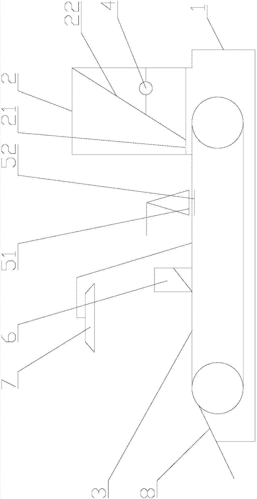
[0014] Such as figure 1 As shown, a sorting particle machine includes a frame 1, a conveying mechanism, a feed bin 2, a vibration mechanism 4, a leveling mechanism, a waste box 6, a lighting lamp 7 and a blanking plate 8, and the conveying mechanism is installed on the frame. The silo, the leveling mechanism, the waste bin and the blanking plate are installed on the frame sequentially along the conveying direction of the conveying mechanism.

[0015] The conveying mechanism has a horizontal working surface 3. In this embodiment, the conveying mechanism is a synchronous belt conveying device. The synchronous belt conveying device includes two synchronous belt pulleys located at the same level and a transmission connection between the two synchronous belt pulleys. Synchronous belt, the upper surface of the synchronous belt is the working surface of the conveying mechanism. Of course, a horizontal support surface can also be directly arranged on the frame, and a cylinder is inst...


PUM


Abstract

The invention discloses a particle sorting machine. The particle sorting machine comprises a stander, a stock bin, a flattening mechanism and a conveying mechanism, wherein the stock bin, the flattening mechanism and the conveying mechanism are respectively installed on the stander, the stock bin and the flattening mechanism are sequentially arranged along the conveying direction of the conveying mechanism, a feeding opening and a discharging opening are formed in the stock bin, the discharging opening is formed in the bottom of the stock bin, the stock bin is connected with a vibrating mechanism, the flattening mechanism is provided with a horizontal flattening surface, the conveying mechanism is provided with a horizontal working surface, the discharging opening and the flattening surface are respectively arranged above the working surface, and a passage which is used for particles to pass through is formed between the flattening surface and the working surface. By adopting the particle sorting machine, not only can the quantity of the particles be adjusted, but also the scattering state of the particles can be adjusted, the inspection by an inspector can be facilitated, the inspection efficiency can be improved, and the inspection precision also can be guaranteed.

Description

technical field [0001] The invention relates to a sorting particle machine. Background technique [0002] Usually, the particles will be piled up on the inspection table for inspection. The inspector will pick out the particles with defects on the surface by observing the surface of the particles. In the existing technology, the inspector needs to spread the piled particles manually and then inspect them one by one. The number of particles is huge, and the spread is also chaotic. It is laborious to inspect, and the inspection efficiency and inspection accuracy cannot be taken into account at the same time. Contents of the invention [0003] The problem to be solved by the present invention is to provide a particle sorting machine to improve the efficiency and accuracy of particle surface defect inspection. [0004] In order to solve the above-mentioned technical problems, the present invention adopts the following technical solutions: a sorting particle machine, comprisin...

Claims


Application Information

Patent Timeline
Patent Type & Authority Applications(China)
IPC IPC(8): B07B13/04B07B13/16
Inventor 郑鑫森华永校宋宝善姚晓峰
Owner 浙江中科光铭光电股份有限公司
Learn More