
Connector structure, female connector and male connector

A technology of male connector and female connector, which is applied in the direction of connection, fixed connection, contact parts, etc., can solve the problems of reducing the height and narrowing of the connecting part, so as to save the height, suppress the reduction of the retention force, and save the space. Effect

Active Publication Date: 2017-03-08
ASAHI DENKA KENKYUSHO
View PDF4 Cites 0 Cited by
  • Summary
  • Abstract
  • Description
  • Claims
  • Application Information

AI Technical Summary

Problems solved by technology

[0004] However, in the case of the conventional connector structure formed by this method, it is difficult to reduce the height of the connecting portion of the two connectors to 1.0 mm or less, and it is also difficult to change the pitch (interval) between the output and input terminals. As narrow as 0.4mm or less, there is a limit to further space saving and height reduction of the connector structure.

Method used


Image

  • Connector structure, female connector and male connector
  • Connector structure, female connector and male connector
  • Connector structure, female connector and male connector

Examples


Embodiment Construction

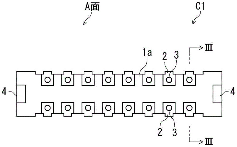
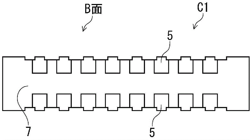
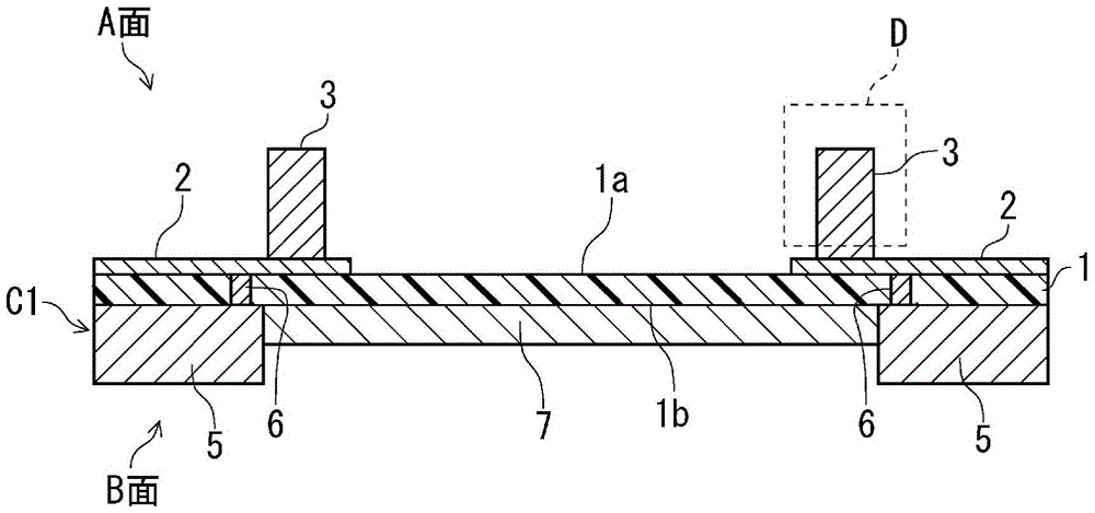
[0061] First, among the male connector and the female connector constituting the connector structure of the present invention, the male connector C1 in which the male terminal portions are arranged in two rows along the longitudinal direction of the connector and the female terminal portions are similarly arranged The basic structure of female connectors C2 in two rows will be described according to the drawings.

[0062] First, the male connector C1 will be described.

[0063] figure 1 It is a plan view showing an example of one surface (hereinafter referred to as A surface) formed by projecting the male terminal portion in the male connector C1; figure 2 is a plan view showing an example of the other side of the male connector C1 (hereinafter referred to as the B side); image 3 is along figure 1 Sectional view of line III-III. Here, the surface B is the back surface of the male connector C1, and this surface is the surface on the mounting side when the male connector C...


PUM


Abstract

Provided are a female connector and a male connector in which mounting pad terminals are arranged on both sides of a mounting side of a circuit board, and a connector structure using them. The female connector (C2) is composed of the following parts: an insulating film (1); a pad part (8) formed on one side (A side) of the insulating film (1); the other side covering the insulating film (1) (B surface) is fixedly installed, and the metal guide member (7) that has been applied with insulating coating; from the position that penetrates the pad part (8) and the insulating film (1) in the thickness direction The female terminal part (E) formed by the slit opening (9) formed; has the width covered by the female terminal part (E), and a through hole formed through the metal guide part (7'); and the insulating film ( 1) Mounting pad terminals formed on both sides of the B surface, protruding from the surface of the metal lead member (7') and electrically connected to the pad portion (8). A connector structure is formed by inserting the male terminal part (D) of the male connector (C1) from the side A of the female connector to the slit opening (9).

Description

technical field [0001] The present invention relates to a new connector structure. More specifically, it relates to a conventional connector which is composed of a male connector and a female connector whose output and input terminals are pulled out in the shape of centipede feet and are sealed with resin as a whole. Compared with the connector structure, the connector structure that achieves a large narrow pitch and height reduction, and also properly ensures the holding force between the male connector and the female connector, the present invention also relates to a connector structure The new structure of the male connector and the female connector can work smoothly when they are respectively soldered and mounted on the rigid circuit board or the flexible circuit board. Background technique [0002] With the development of miniaturization, thinning, multi-functionality and light weight of various electrical and electronic equipment, the requirements for miniaturization a...

Claims


Application Information

Patent Timeline
Patent Type & Authority Patents(China)
IPC IPC(8): H01R12/79H01R12/71H01R12/77
CPCH01R12/79H05K1/147H05K3/341H05K2201/10189H01R12/62H05K3/365Y02P70/50H01R12/71H01R12/77H01R13/03
Inventor 沟口昌范前田龙
Owner ASAHI DENKA KENKYUSHO
Learn More