
Light emitting diode (LED) corrugated lamp

A corrugated lamp and lamp body technology, which is used in decorative arts, cooling/heating devices of lighting devices, lighting and heating equipment, etc., can solve the problems of destroying the architectural style, inability to match tiles, and large gaps, and achieve easy installation and positioning. , Flexible layout, good lighting projection effect

Inactive Publication Date: 2015-07-01
CHONGQING ENWEIXI IND DEV
View PDF0 Cites 0 Cited by
  • Summary
  • Abstract
  • Description
  • Claims
  • Application Information

AI Technical Summary

Problems solved by technology

The tiles of the tiled roof are arranged in such a way that the curved tiles are buckled one on top of the other, and the crescent-shaped gap between the two tiles is the installation space of the tile lamp. The two sheets of the tile lamp are inserted into the Yes, however, since the basic shape of the LED corrugated light on the market is fixed, it cannot be matched with tiles of different radians. After installation, the gap between the building and the building is too large, which will damage the overall architectural style.

Method used


Image

  • Light emitting diode (LED) corrugated lamp
  • Light emitting diode (LED) corrugated lamp
  • Light emitting diode (LED) corrugated lamp

Examples


Embodiment Construction

[0021] The preferred embodiments of the present invention will be described in detail below with reference to the accompanying drawings.

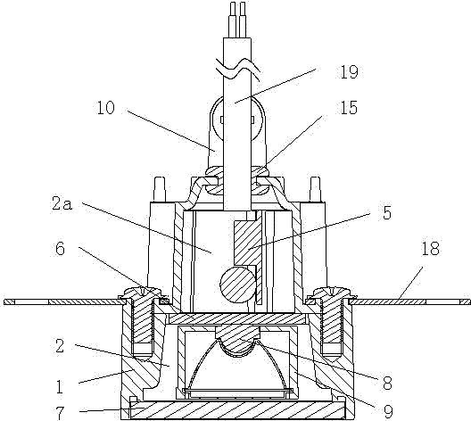
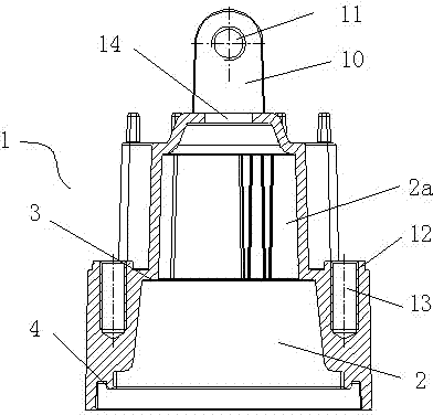
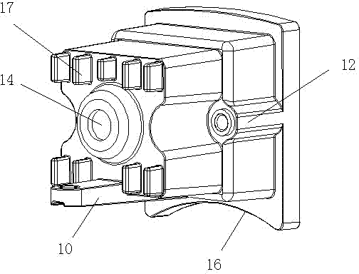
[0022] Such as figure 1 Shown is a schematic structural view of an embodiment of the LED corrugated light of the present invention. The LED corrugated lamp of this embodiment includes a lamp body assembly and a light source assembly. The lamp body assembly includes a housing 1. The housing 1 is provided with an installation cavity 2 for installing the light source assembly. The installation cavity 2 is provided with a first installation platform 3 and a second installation platform 4 in sequence from the inside to the outside, and the first installation platform 3 and the bottom of the installation cavity 2 is provided with a power board installation cavity 2a. The light source assembly includes a power board 5 installed in the power board installation cavity 2a, a light source board 6 installed on the second installation platform 4, and ...


PUM


Abstract

The invention discloses a light emitting diode (LED) corrugated lamp. The LED corrugated lamp comprises a lamp body module and a light source module, the lamp body module comprises a shell, a mounting cavity for mounting the light source module is arranged in the shell, the mounting cavity is provided with a first mounting platform and a second mounting platform in sequence from inside to outside, a power supply plate mounting cavity is arranged between the first mounting platform and the bottom of the mounting cavity, the light source module comprises a power supply plate, a light source plate and a transparent lampshade, the power supply plate is mounted in the power supply plate mounting cavity, the light source plate is disposed on the second mounting platform, the transparent lampshade is disposed on the first mounting platform, light emitting diodes (LEDs) are arranged on the light source plate, a lens module which corresponds to the LEDs is arranged between the transparent lampshade and the light source plate, an adjusting plate is arranged on the bottom surface of the shell, screw holes are formed in the adjusting plate, protruding columns are arranged on two opposite side surfaces of the shell respectively, and threaded holes for mounting screws are designed in the protruding columns.

Description

technical field [0001] The invention belongs to the technical field of semiconductor lighting equipment, and in particular relates to an LED corrugated lamp. Background technique [0002] LED corrugated light, also known as tile light, is a kind of projection light. It uses high-power LED as the light source. The shell part is made of aluminum alloy die-casting parts. The outline, especially for the lighting of the eaves at night, is often used in landscape decorations such as landscape buildings, ancient buildings, glazed tiles, villas and parks. The tiles of the tiled roof are arranged in such a way that the curved tiles are buckled one on top of the other, and the crescent-shaped gap between the two tiles is the installation space of the tile lamp. The two sheets of the tile lamp are inserted into the Yes, however, since the basic shape of the LED corrugated light on the market is fixed, it cannot be matched with tiles of different radians. After installation, the gap b...

Claims


Application Information

Patent Timeline
Patent Type & Authority Applications(China)
IPC IPC(8): F21S8/00F21V19/00F21V14/02F21V21/005F21V29/76F21Y101/02F21Y115/10
CPCF21S8/00F21V14/02F21V17/12F21V19/001F21V21/00F21W2121/004
Inventor 王邵灵姚家德黄尔建
Owner CHONGQING ENWEIXI IND DEV
Learn More