Light emitting diode bulb with central axis bidirectional convection heat dissipation structure

A technology of light emitting diodes and heat dissipation structures, which is applied to semiconductor devices, lamp shades, light sources, etc. of light emitting elements, can solve the problems of user burns, difficult manufacturing, and high production costs, and achieves extended service life, low lamp housing structure, and avoidance of burns. Effect

Inactive Publication Date: 2015-06-24
SKYNET ELECTRONICS
View PDF9 Cites 65 Cited by
  • Summary
  • Abstract
  • Description
  • Claims
  • Application Information

AI Technical Summary

Problems solved by technology

[0007] (4) However, in fact, after the light-emitting diode bulb developed by RAMBUS INC. is assembled, the heat dissipation lamp holder A10, the outer heat dissipation sleeve A15 and the inner heat dissipation sleeve A16 are connected into one body, and the All the heat dissipation fins A102 on the heat dissipation lamp holder A10 are exposed on the outer edge of the light-emitting diode bulb. According to the basic principle of heat conduction effect, the heat energy is conducted to the area with a large temperature difference. Therefore, the heat generated by these light-emitting diodes A131 Most of the heat energy is still conducted to these cooling fins A102 through the bottom surface of the LED circuit board, and then dissipated into the surrounding air. Therefore, when the temperature of these LEDs A131 gradually rises, and gradually accumulates in these cooling fins When the A102 is installed, these heat dissipation fins A102 will still have a very high temperature, which is very easy to be accidentally touched by the user, resulting in a scalding accident, and it will take a lot of effort to install the upper convection hole A151 and the lower convection hole The heat convection channel formed between A104 cannot actually exert the expected heat dissipation effect
[0008] (5) In addition, after the LED light bulb developed by RAMBUS INC. is assembled, since the drive circuit board is installed in the bottom of the heat sink lamp holder A10, most of the LEDs produced by these LEDs A131 When the heat energy is transferred to the heat dissipation fins A102 through the bottom surface of the LED circuit board, it also means that the heat energy has been transferred to the bottom of the heat dissipation lamp holder A10. Accordingly, the temperature in the bottom of the heat dissipation lamp holder A10 As the temperature of these light-emitting diodes A131 gradually rises, the drive circuit board inside will be baked at a high temperature. If things go on like this, the life of many electronic components on the drive circuit board will inevitably be shortened, and the life of the drive circuit board will inevitably be greatly reduced. Lifespan of LED bulbs
[0014] Inventor's aforementioned light-emitting diode light bulb structure, see again figure 2 and image 3 As shown, although it is true that the heat dissipation efficiency of these LEDs 411 in the LED light bulb can be effectively improved without increasing the cost, it is not easy to burn the user, and the service life of the driving circuit board 33 is ensured, and the LED circuit A large amount of heat energy generated by the board 41 and the light emitting diodes 411 on it can exchange heat with the surrounding cold air outside the bulb in the manner of heat conduction and heat convection at the same time, so as to greatly improve the overall heat dissipation efficiency of the bulb; During the actual operation, it was found that since the configuration of the light-transmitting cover 50 is extremely difficult to be integrally formed by glass or plastic materials, not only there are still problems of difficulty in manufacture and high production cost, but also its overall structure is too complicated. There are still problems of too many components and complicated assembly procedures. Therefore, the inventor thinks and simplifies the structure of the entire light-emitting diode bulb, in order to be able to use heat conduction and heat convection at the same time under the extremely simple structural conditions. Through the above-mentioned two-way convection heat dissipation channel on the central axis, the above-mentioned effective heat dissipation and the purpose of avoiding burns can be achieved

Method used


Image

  • Light emitting diode bulb with central axis bidirectional convection heat dissipation structure
  • Light emitting diode bulb with central axis bidirectional convection heat dissipation structure
  • Light emitting diode bulb with central axis bidirectional convection heat dissipation structure

Examples


Embodiment Construction

[0042] In order to facilitate the examiner to further understand and understand the purpose, structure and effect of the present invention, the following examples are given in conjunction with the drawings, and the details are as follows:

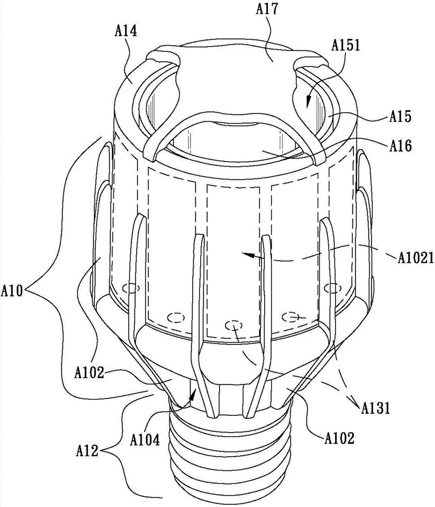
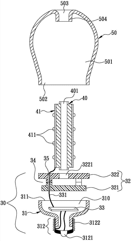
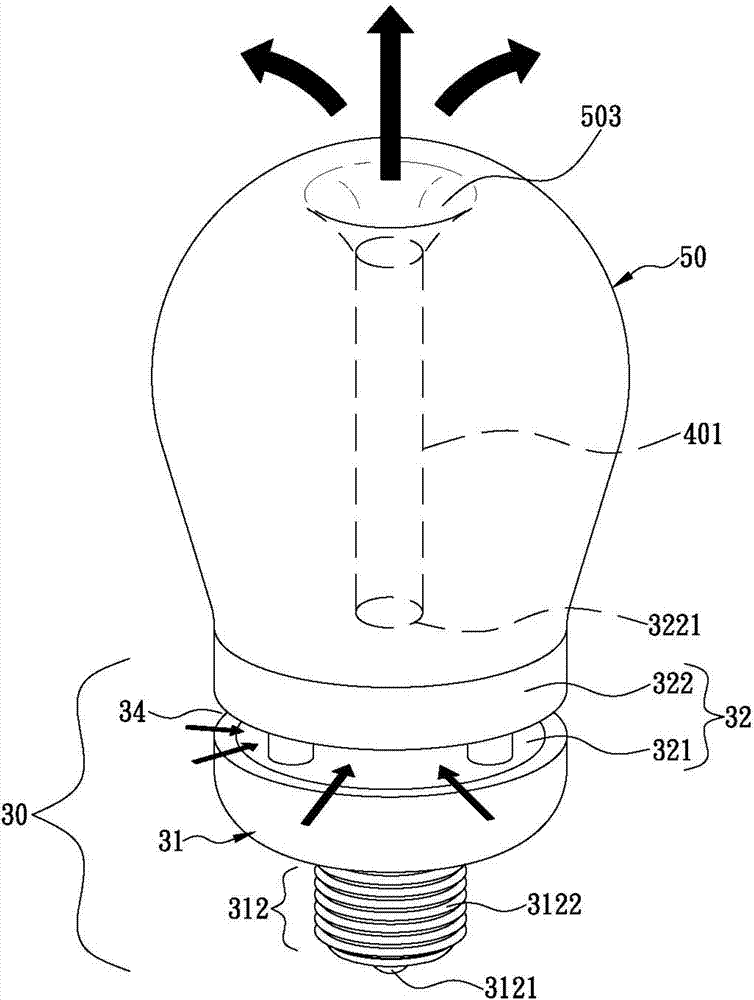
[0043] like figure 2 and image 3 As shown, the inventor's light-emitting diode bulb with a central axis bidirectional convection heat dissipation structure has a minimal structure. The inventor divides the entire light-emitting diode bulb into two parts to make an upper lamp housing and a lower lamp housing, and then the The upper lamp housing and the lower lamp housing are combined to make the structure of the bulb extremely simplified, thereby effectively reducing the production difficulty and production cost, and the related heat dissipation elements can be completely covered in the bulb, so as to effectively prevent users from touching these components. Accidents of burns due to heat dissipation components.

[0044] In the first pre...


PUM


Abstract

An LED bulb includes a lower cover having ventilation holes formed at outer periphery thereof, and a first coupling opening formed at top side thereof; a separating unit provided within the lower cover at a position between lower edges of the ventilation holes and bottom side of the lower cover, and having a convection pathway formed at top side thereof; a heat sink having bottom end positioned on top side of the separating unit; and an upper cover having top side formed with convection hole corresponding to top end of the heat sink, and a second coupling opening formed at bottom side thereof. When the second and first coupling openings are coupled with each other, the upper and lower covers are assembled together to form a central axis bidirectional convection heat dissipation pathway sequentially through the ventilation hole, the convection pathway, the heat sink and the ventilation hole accordingly.

Description

technical field [0001] The invention relates to a light-emitting diode light bulb, in particular to a light-emitting diode light bulb with a central axis bidirectional convection heat dissipation structure. Background technique [0002] In recent years, as the manufacturing cost of various high-brightness LEDs has become cheaper, many light bulb manufacturers have begun to use LEDs as light-emitting elements to produce LED bulbs with environmental protection and energy-saving demands. However, due to the light-emitting diodes The process will generate heat that is difficult to ignore. Therefore, once the light-emitting diode bulb cannot discharge the heat generated by the light-emitting diode smoothly, it will inevitably cause the temperature of the light-emitting diode itself to remain high. This leads to serious material aging and light decay of the light-emitting diode, which greatly shortens the service life. In order to improve this problem, although many industry comp...

Claims


Application Information

Patent Timeline
Patent Type & Authority Applications(China)
IPC IPC(8): F21S2/00F21V29/503F21V29/74F21V23/00F21Y101/02
CPCF21S2/00F21V23/003F21Y2101/00F21V29/503F21V3/02F21V17/002F21V19/004F21V29/506F21V29/83F21K9/23F21Y2115/10F21Y2107/40
Inventor 梁锦宏
Owner SKYNET ELECTRONICS
Why Eureka
Try Eureka