Manufacturing method for concrete expansion joint dual waterstop structure

A manufacturing method and concrete technology, which is applied in earthwork drilling, infrastructure engineering, water conservancy engineering, etc., can solve problems such as extended construction period, irregular deformation of concrete tanks, and difficult cleaning, so as to reduce construction period, save installation procedures, and prevent fractures The effect of interface misalignment

Inactive Publication Date: 2015-06-24
防城港市明隆辉混凝土有限公司
View PDF2 Cites 1 Cited by
  • Summary
  • Abstract
  • Description
  • Claims
  • Application Information

AI Technical Summary

Problems solved by technology

[0002] In existing concrete structures, such as retaining dams, reservoirs, subways, culverts, sluices, tunnels and other underground projects, due to the inability to pour continuously or the deformation of the foundation settlement (earthquake), or the concrete caused by temperature changes Expansion joints and deformation joints should be reserved during pouring due to thermal expansion and contraction of components, and anti-leakage measures should be taken for these gaps to prevent external water or groundwater from leaking into the structural space. A concrete groove is set between the stage concrete and the second stage concrete, and soft asphalt and copper sheets or rubber waterstops are arranged in the groove. However, this method requires prefabricated concrete grooves. The 3 sides of the groove are chiselled, which will prolong the construction period and increase the labor. At the same time, because the length (height) of each concrete groove is generally only 50-100cm, the expansion gap must be composed of multiple concrete grooves, so there will be many. Horizontal gaps and irregular deformation of multiple concrete grooves will cause run-off of soft asphalt poured in the subsequent sequence, and it is difficult to clean up

Method used


Image

  • Manufacturing method for concrete expansion joint dual waterstop structure
  • Manufacturing method for concrete expansion joint dual waterstop structure
  • Manufacturing method for concrete expansion joint dual waterstop structure

Examples


Embodiment

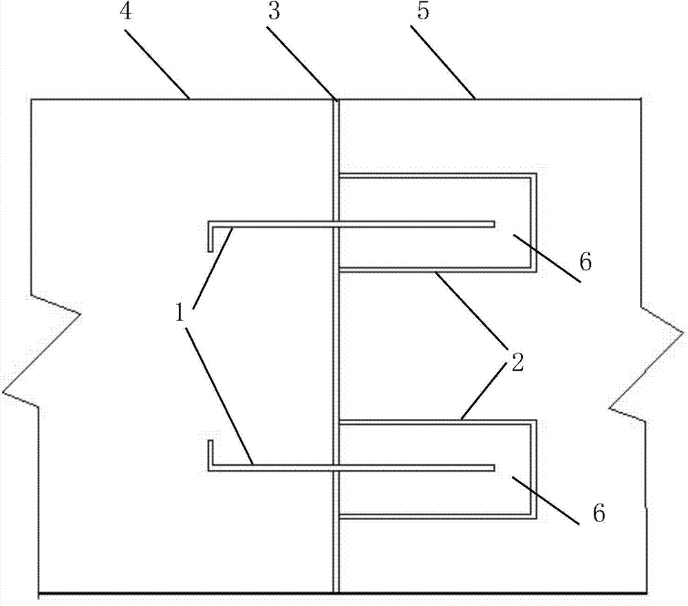
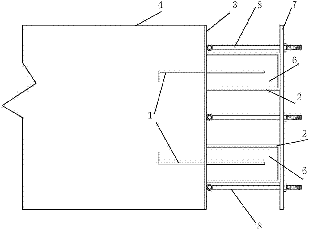
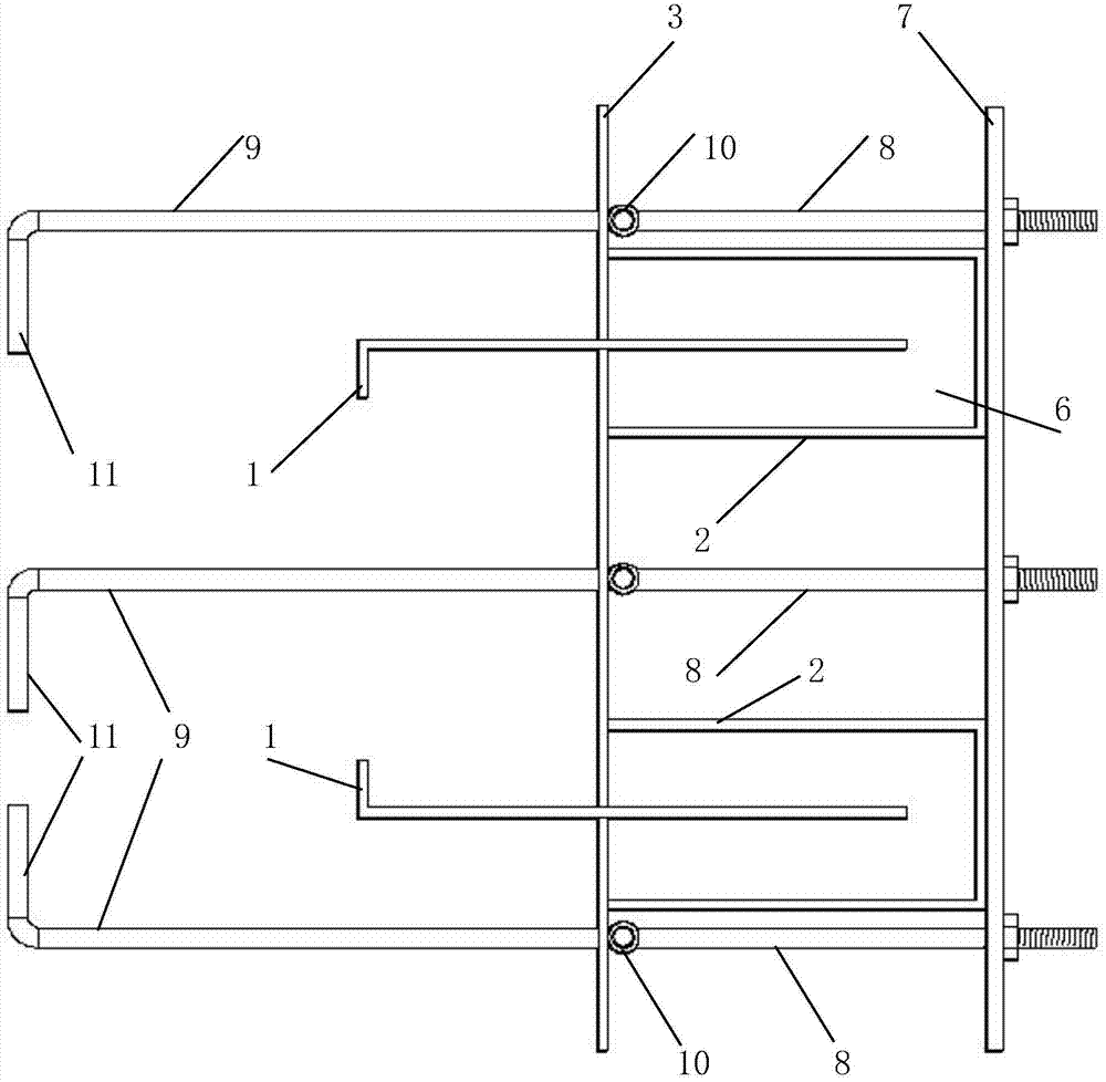
[0044] Embodiment, referring to the accompanying drawings: a concrete expansion joint double water-stop structure, including a deformation piece 1, a channel steel 2, two deformation pieces 1 are provided on the concrete section, and the two deformation pieces 1 are vertically arranged at a predetermined distance , half of which is pre-embedded in the first-stage concrete 4, and the other half protrudes from the concrete section and is respectively arranged in the corresponding channel steel 2, and the channel steel 2 is provided with asphalt 6; the channel steel 2 Linoleum 3 is provided on the opening surface and the section of the first-stage concrete 4 .

[0045]Further, the deformable sheet 1 is in the form of a rectangular plate with a width of 30-60 cm and a length equal to the height of the concrete section. The side poured into the concrete is bent at 90° with a bending height of 2-5 cm. Two deformable sheets 1 are respectively arranged on The distance between the two ...


PUM

PropertyMeasurementUnit
Thicknessaaaaaaaaaa
Total thicknessaaaaaaaaaa
Thicknessaaaaaaaaaa

Abstract

The invention relates to an underground (underwater) building waterproof device, in particular to a manufacturing method for a concrete expansion joint dual waterstop structure. The structure comprises transformation sheets and steel channels. The manufacturing method is characterized in that a concrete fracture surface is provided with the two transformation sheets, the two transformation sheets are longitudinally arranged in a set spaced mode, one half of each transformation sheet is buried in primary concrete, the other half of each transformation sheet is protruded out of the concrete fracture surface and arranged in the corresponding steel channel, pitch is arranged in the steel channels, the opening faces of the steel channels and the primary concrete fracture surfaces are provided with asphaltic felts, exposed fixing parts are removed after the pitch is cooled, and then secondary concrete is arranged. The water seepage problem caused by uneven settlement or diastrophism of the stratum of a water conservancy project can be solved, labor can be saved, and the construction period can be shortened.

Description

technical field [0001] The invention relates to an underground (underwater) building waterproof device, in particular to a method for manufacturing a concrete expansion joint double water stop structure. Background technique [0002] In existing concrete structures, such as retaining dams, reservoirs, subways, culverts, sluices, tunnels and other underground projects, due to the inability to pour continuously or the deformation of the foundation settlement (earthquake), or the concrete caused by temperature changes Expansion joints and deformation joints should be reserved during pouring due to thermal expansion and contraction of components, and anti-leakage measures should be taken for these gaps to prevent external water or groundwater from leaking into the structural space. A concrete groove is set between the stage concrete and the second stage concrete, and soft asphalt and copper sheets or rubber waterstops are arranged in the groove. However, this method requires pre...

Claims


Application Information

Patent Timeline
IPC IPC(8): E02B3/16E02B7/54E21D11/38E02D31/02
CPCE02B3/16E02B7/54E02D31/02E21D11/38
Inventor 张朝利
Owner 防城港市明隆辉混凝土有限公司
Why Eureka
Try Eureka