
Powerful brake device

A braking device, powerful technology, applied in the hoisting device and other directions, can solve the problems of unsatisfactory requirements and small driving force, and achieve the effects of large braking torque, short braking time and reduced power loss

Inactive Publication Date: 2015-06-24
河南省汇隆精密设备制造股份有限公司
View PDF8 Cites 3 Cited by
  • Summary
  • Abstract
  • Description
  • Claims
  • Application Information

AI Technical Summary

Problems solved by technology

[0002] The electric winch is the most common mechanical appliance driven by the electric system. It pulls the goods through the reel. The motor of the ordinary winch rotates and connects the intermediate transmission shaft through the spline. The intermediate transmission shaft is connected to the reducer, and the reducer passes through The internal and external gears are meshed and transmitted to the reel, thereby driving the reel to rotate. Most ordinary electric winches can provide a small driving force. Generally, the operating speed is 20~30m / min, the braking torque is 6000NM, and the braking time is 0.5S. For left and right occasions, the current situation is: a rail trolley runs at a high speed of 30~35m / S, and the braking time is required to be less than 0.06S to pull the trolley back to its original position. The braking torque needs to be 14000NM, that is, it needs a strong and fast braking, the existing electric winch device will not meet the requirements

Method used


Image

  • Powerful brake device

Examples


Embodiment 1

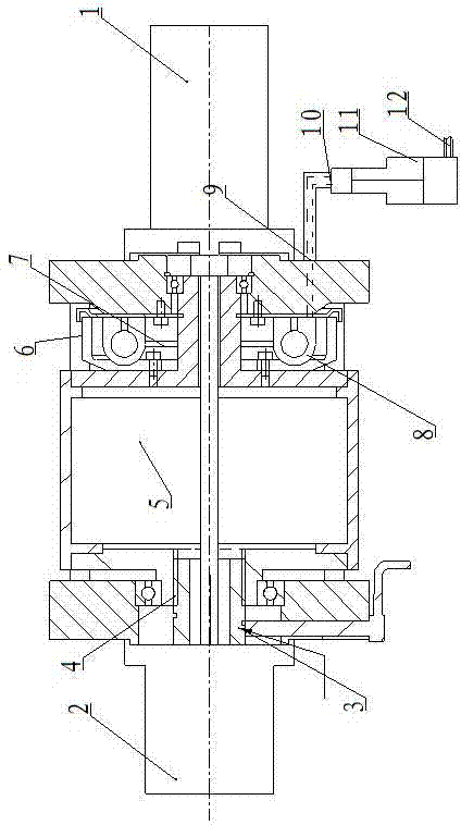
[0014] Such as figure 1 Shown: a strong braking device, which includes a motor 1, characterized in that: the motor 1 is provided with a speed reducer 2, the speed reducer 2 is connected with a clutch 3, and the output end of the clutch 3 passes through The spline 4 is connected to the reel 5, and the reel 5 is connected with a brake device 6, the hub of the brake device 6 is fixed on the reel 5 by bolts, and the brake device 6 is provided with a brake shoe 7 and a pump 8, the sub-pump 8 is connected to a high-pressure oil inlet 9, the high-pressure oil inlet 9 is connected to a high-pressure oil outlet 10, and the high-pressure oil outlet 10 is connected to a gas-liquid booster device 11, and the gas-liquid The pressure booster 11 is connected with a low-pressure gas 12 .

[0015] The invention is simple in design, the motor drives the reducer, the reducer is connected to the input end of the clutch, and the output end of the clutch is connected to the reel through a spline,...

Embodiment 2

[0017] Such as figure 1 Shown: a strong braking device, which includes a motor 1, characterized in that: the motor 1 is provided with a speed reducer 2, the speed reducer 2 is connected with a clutch 3, and the output end of the clutch 3 passes through The spline 4 is connected to the reel 5, and the reel 5 is connected with a brake device 6, the hub of the brake device 6 is fixed on the reel 5 by bolts, and the brake device 6 is provided with a brake shoe 7 and a pump 8, the sub-pump 8 is connected to a high-pressure oil inlet 9, the high-pressure oil inlet 9 is connected to a high-pressure oil outlet 10, and the high-pressure oil outlet 10 is connected to a gas-liquid booster device 11, and the gas-liquid The pressure booster 11 is connected with a low-pressure gas 12 .

[0018] The brake shoe 7 and the slave cylinder 8 are fixed on the upper side of the base.

[0019] The two ends of the reel 5 are respectively provided with a bearing and are fixed on the upper side of t...


PUM


Abstract

The invention relates to a powerful brake device. The powerful brake device comprises a motor. The motor is provided with a speed reducer which is connected with a clutch. The output end of the clutch is connected with a drum through a spline. The drum is connected with a brake device. A hub of the brake device is fixed to the drum through bolts. The brake device is provided with a brake shoe and a wheel cylinder. The wheel cylinder is connected with a high-pressure oil inlet which is connected with a high-pressure oil outlet. The high-pressure oil outlet is connected with a gas-liquid pressurization device which is connected with low-pressure gas. According to the powerful brake device, the cutch and the high-power brake device are mainly added, the clutch is added to the drive end of a special electric winch, the brake device is arranged at the other end of the special electric winch, the rotation inertia is reduced, the power consumption is lowered in the braking process, large braking force is provided through drum type braking, the drum rotating at a high speed is rapidly braked, the gas-liquid pressurization device provides braking power, and the powerful brake device has the advantages of being high in running speed, short in braking time and large in braking torque.

Description

technical field [0001] The invention belongs to the field of mechanical design, in particular to a braking device, in particular to a powerful braking device. Background technique [0002] The electric winch is the most common mechanical appliance driven by the electric system. It pulls the goods through the reel. The motor of the ordinary winch rotates and connects the intermediate drive shaft through the spline. The intermediate drive shaft is connected to the reducer, and the reducer passes through The internal and external gears are meshed and transmitted to the reel, thereby driving the reel to rotate. Most ordinary electric winches can provide a small driving force. Generally, the operating speed is 20~30m / min, the braking torque is 6000NM, and the braking time is 0.5S. For left and right occasions, the current situation is: a rail trolley runs at a high speed of 30~35m / S, and the braking time is required to be less than 0.06S to pull the trolley back to its original p...

Claims


Application Information

Patent Timeline
Patent Type & Authority Applications(China)
IPC IPC(8): B66D5/08
CPCB66D5/08
Inventor 李超辉谢坚刘增粮杨惠明
Owner 河南省汇隆精密设备制造股份有限公司
Learn More