
Cleaner head

A technology for cleaners and agitators, applied in cleaning equipment, vacuum cleaners, suction nozzles, etc., can solve problems such as noise generation and agitator vibration

Inactive Publication Date: 2015-06-17
DYSON TECH LTD
View PDF9 Cites 2 Cited by
  • Summary
  • Abstract
  • Description
  • Claims
  • Application Information

AI Technical Summary

Problems solved by technology

So when the agitator rotates, the agitator vibrates and makes noise

Method used


Image

  • Cleaner head
  • Cleaner head
  • Cleaner head

Examples


Embodiment Construction

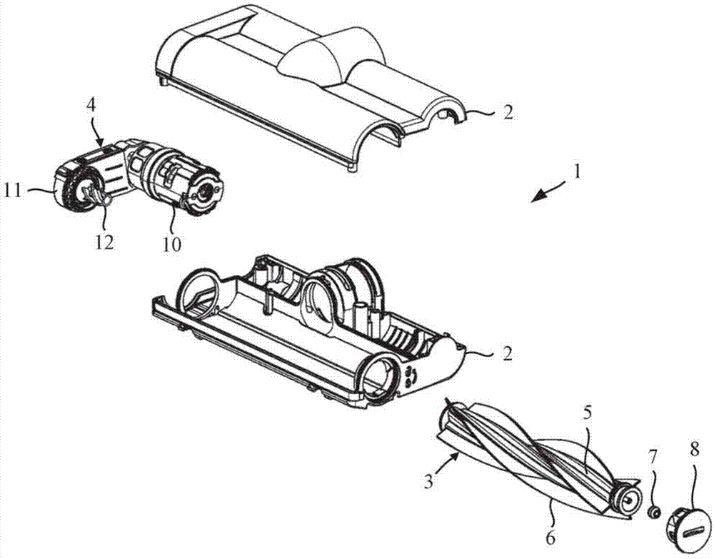
[0020] figure 1 The cleaner head 1 includes a housing 2 in which an agitator 3 and a drive assembly 4 are installed.

[0021] The agitator 3 includes an elongated body 5 to which bristles, beating strips or other implements 6 for agitating a clean surface are attached. The agitator 3 is mounted at one end to a sleeve 7 which is located in a removable cover 8. The opposite end of the agitator 3 is mounted to a drive head 12 forming a part of the drive assembly 4.

[0022] The driving assembly 4 includes a motor 17 and a transmission device 11, and the transmission device 18 is used to transmit the torque generated by the motor 17 to the agitator 3. Among other components, the transmission device 11 includes a drive head 12 that is engaged with the agitator 3. The drive head 12 is thus responsible for transmitting the torque generated by the drive assembly 4 to the agitator 3. Except for the drive head 12, the details of the drive assembly 4 are not the focus of the present invent...


PUM


Abstract

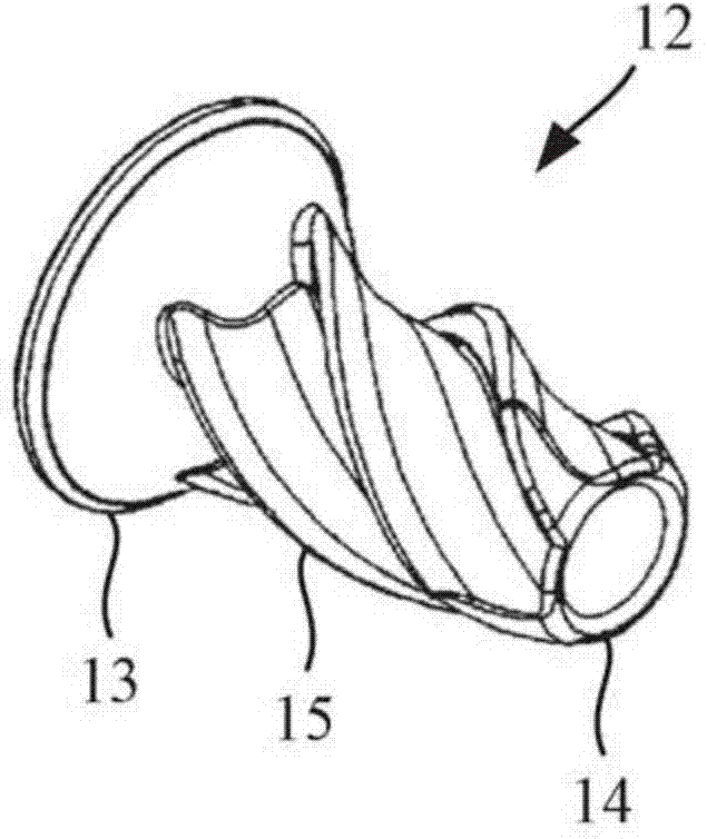
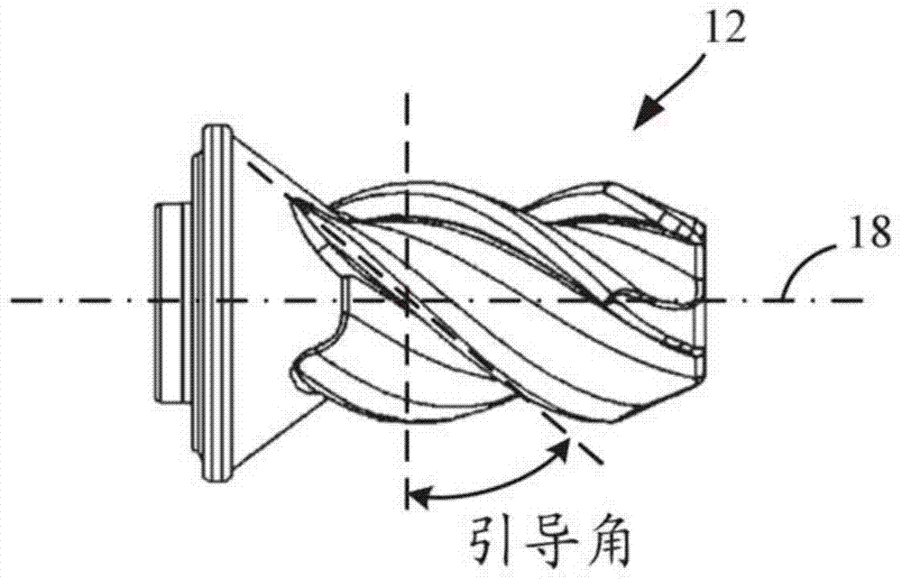
A cleaner head 1 comprising a housing 2, an agitator 3 and a drive assembly 4 for driving agitator 3. Drive assembly 4 comprises a dog 12 for transmitting torque to the agitator 3. One of the dog 12 and the agitator 3 comprises a tapered head 13, a shank 14 that extends from head 13, and a screw thread 15 formed around shank 14. The other of the dog 12 and the agitator 3 comprises a bore (19, Fig 5) having a countersink (20) and a complementary screw thread (21) formed around a wall of the bore (19). Shank 14 projects into bore (19) and the two threads 15 (21) mate such that, as dog 12 rotates, the agitator screws on to the dog and the tapered head 13 mates with the countersink (20). The screw thread has a maximum lead angle (see fig 3) of 60 degrees and each screw thread 15 (21) has a plurality of starts (22) and turns through a maximum angle of 360 degrees and a minimum angle of 120 degrees. Agitator 3 may be removed from cleaner head 1 and each screw thread has a buttress thread form. Other elements include electric motor 10, transmission 11, bushing 7 and removable cap 8.

Description

Technical field [0001] The invention relates to a cleaner head having a stirrer and a drive assembly for driving the stirrer. Background technique [0002] The cleaner head of an appliance such as a vacuum cleaner or a floor wiper may include an agitator driven by a drive assembly. The drive assembly often includes a drive head for transmitting the torque generated by the drive assembly to the agitator. The problem with the existing cleaner head is that there is often a certain degree of play between the drive head and the agitator. Therefore, when the agitator rotates, the agitator vibrates and generates noise. Summary of the invention [0003] The present invention provides a cleaner head, including an agitator and a driving assembly for driving the agitator, the driving assembly includes a driving head (dog) for transmitting torque to the agitator, wherein one of the driving head and the agitator includes A tapered head, a shank extending from the head, and a thread formed a...

Claims


Application Information

Patent Timeline
IPC IPC(8): A47L9/04
CPCA47L9/0411A47L9/0477
Inventor W.克尔A.斯丘斯
Owner DYSON TECH LTD
Learn More