
Renewable energy source cooling, heating and power microgrid system and control method

A renewable energy, cooling and heating technology, applied in wind power generation, energy storage, refrigerators, etc., can solve the problems of low energy utilization rate, no consideration of waste heat recovery, waste of electric energy, etc.

Active Publication Date: 2015-06-17
SHANDONG UNIV
View PDF5 Cites 27 Cited by
  • Summary
  • Abstract
  • Description
  • Claims
  • Application Information

AI Technical Summary

Problems solved by technology

Due to the strong coupling of the electricity and heat output of the internal combustion generator set, no matter what operation mode is used, the full utilization of electricity and heat cannot be guaranteed.
Moreover, both modes require real-time adjustment of the output of the gas turbine or internal combustion engine, so the reliability of the system is poor, the unit cannot always operate in the high-efficiency area, the energy utilization rate is low, and it will also affect the life of the internal combustion engine
[0007] Most of the current micro-grid systems only consider the control and use of electric energy. However, the micro-grid system composed of photovoltaic, wind power, and energy storage is greatly affected by the weather. If it cannot be connected to the Internet, it will cause waste of electric energy.
However, micro-grid systems equipped with internal combustion generator units often do not consider waste heat recovery, resulting in a large amount of heat loss

Method used


Image

  • Renewable energy source cooling, heating and power microgrid system and control method
  • Renewable energy source cooling, heating and power microgrid system and control method
  • Renewable energy source cooling, heating and power microgrid system and control method

Examples


Embodiment Construction

[0052] Below in conjunction with accompanying drawing and embodiment the present invention will be further described:

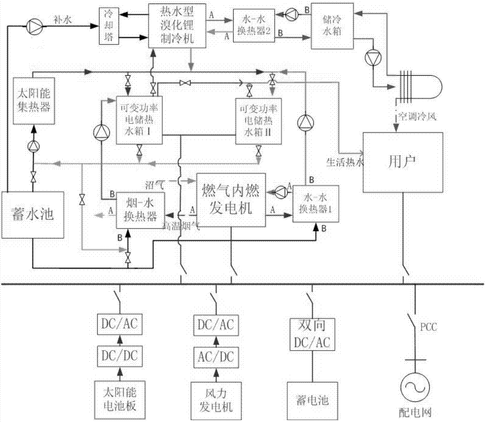
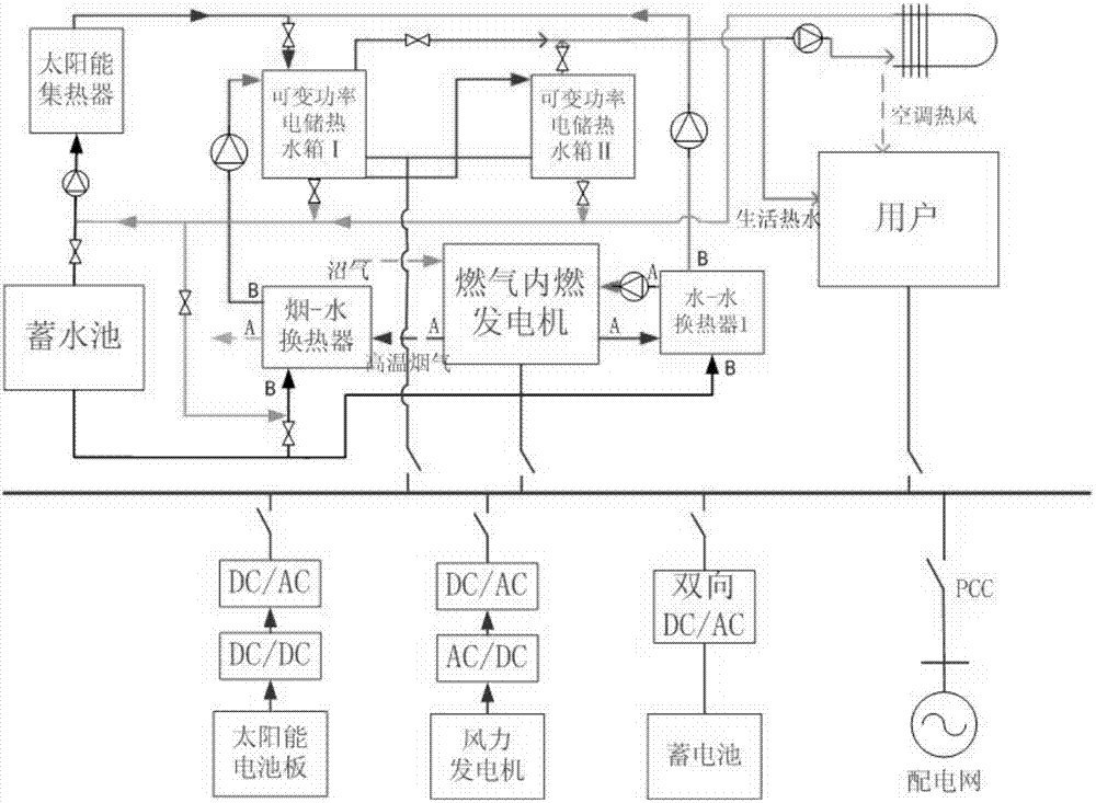
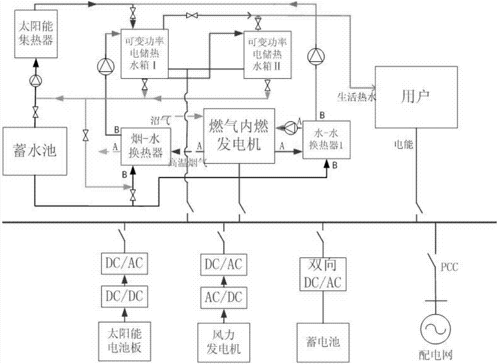
[0053] The cold and hot power microgrid system is composed of two parts: the electric module and the cold / heat module.

[0054] Electric modules include solar panels, wind generators, gas internal combustion generator sets, battery packs, electric hot water storage tanks, electric loads, etc. The power generation and energy storage units are connected together by an AC bus (380V, 50Hz). The specific connection method is as figure 1 Shown: The solar power generation system is connected to the AC bus bar after DC-DC-AC conversion, the wind power generator is connected to the AC bus bar after AC-DC-AC conversion, the gas internal combustion generator set is directly connected to the AC bus bar, and the battery pack is connected to the AC bus bar through two-way DC - The AC converter is connected to the AC bus. The AC bus is connected to the distribution netwo...


PUM


Abstract

The invention discloses a renewable energy source cooling, heating and power microgrid system and a control method. The renewable energy source cooling, heating and power microgrid system comprises a power module and a cooling / heating module. According to the power module, a solar power generation system is sequentially connected with a DC / DC converter and a DC / AC converter in series and then connected with an AC bus, a wind power generation system is sequentially connected with an AC / DC converter and a DC / AC converter and then connected with the AC bus, a gas internal combustion generation system is directly connected with the AC bus, a storage battery pack is connected with the AC bus through a bi-directional DC / AC converter, variable power electricity storage hot water tanks are connected with the AC bus, and the AC bus is connected with a power distribution network through a PCC. The renewable energy source cooling, heating and power microgrid system and the control method have the advantages that clean renewable energy sources such as methane, wind energy and solar energy are adopted as energy sources of a cooling, heating and power microgrid, no pollution is caused to the environment, operation cost is very low, and the application range is wide; by the adoption of a multi-microsource energy supply mode, the problem of capacity allocation redundancy of a single energy supply system can be solved.

Description

technical field [0001] The invention relates to the technical field of renewable energy power generation, in particular to a multi-energy-driven renewable energy cooling, heating and power microgrid system and a control method. Background technique [0002] 1. The micro-grid system of cooling, heating and electricity is based on the cascade utilization of energy and the coordinated operation of various micro-sources. The multi-energy forms cooperate with each other to provide users with three kinds of energy: cold, heat and electricity at the same time, which can not only improve the efficiency of the system Operating efficiency, reducing energy waste, can also greatly improve the stability of system operation. [0003] 2. Most of my country's combined cooling, heating and power systems use gas turbines as prime movers, but when the capacity is small (such as 30kW to 50kW), internal combustion engines have obvious advantages over micro gas turbines in terms of efficiency, pe...

Claims


Application Information

Patent Timeline
IPC IPC(8): H02J3/00H02S10/10H02S10/20H02J3/32F25B29/00
CPCF25B29/00H02J3/32H02J3/381H02J3/46Y02E10/50Y02E10/76Y02E70/30
Inventor 张承慧石可颂孙波魏大钧陈阿莲
Owner SHANDONG UNIV
Learn More