
Tunable three-ring cascade filter

A filter and cascade technology, applied in the field of integrated optics, can solve the problems of large bandwidth, large wavelength tuning, large heating current, etc., and achieve the effect of low crosstalk and high side mode suppression ratio

Inactive Publication Date: 2015-06-17
INST OF SEMICONDUCTORS - CHINESE ACAD OF SCI
View PDF2 Cites 16 Cited by
  • Summary
  • Abstract
  • Description
  • Claims
  • Application Information

AI Technical Summary

Problems solved by technology

Due to the reliability problems of MEMS filters, MEMS devices cannot be industrialized in the end
FBG filters do not have the problem of alignment with optical fibers, and have been commercially available. However, the tuning range of FBG is very small and cannot meet the requirements of wide-range wavelength tuning.
Acousto-optic tunable filters have also been commercially available to achieve multi-wavelength frequency selection, but there are problems such as large bandwidth, high side lobes, and frequency shift.
Active tunable filters have great potential for ultra-high speed and narrow bandwidth, but their requirements for temperature and current stability are still a problem
In 2008, Joonoh Park et al. from Kwangwoon University in South Korea reported a thermal-optic photonics based on a polymer Ploymer waveguide coupled microring on IEEE Photonics Technology Letters, VOL.20, NO.12, 2008, pp.988-990. Tunable filter, the specific structure is a single waveguide coupling double microring structure, and the two microrings are also in a coupling state, its disadvantage is that the filtering spectrum is a multi-peak envelope structure, and the filtering spectrum with high side mode suppression ratio cannot be realized type
Although the single microring resonator filter based on SOI photonic wire waveguide has the advantages of small size and narrow passband bandwidth, its disadvantage is that it needs a large heating current to obtain relatively large wavelength tuning.

Method used


Image

  • Tunable three-ring cascade filter
  • Tunable three-ring cascade filter
  • Tunable three-ring cascade filter

Examples


Embodiment Construction

[0026] In order to make the object, technical solution and advantages of the present invention clearer, the present invention will be further described in detail below in conjunction with specific embodiments and with reference to the accompanying drawings.

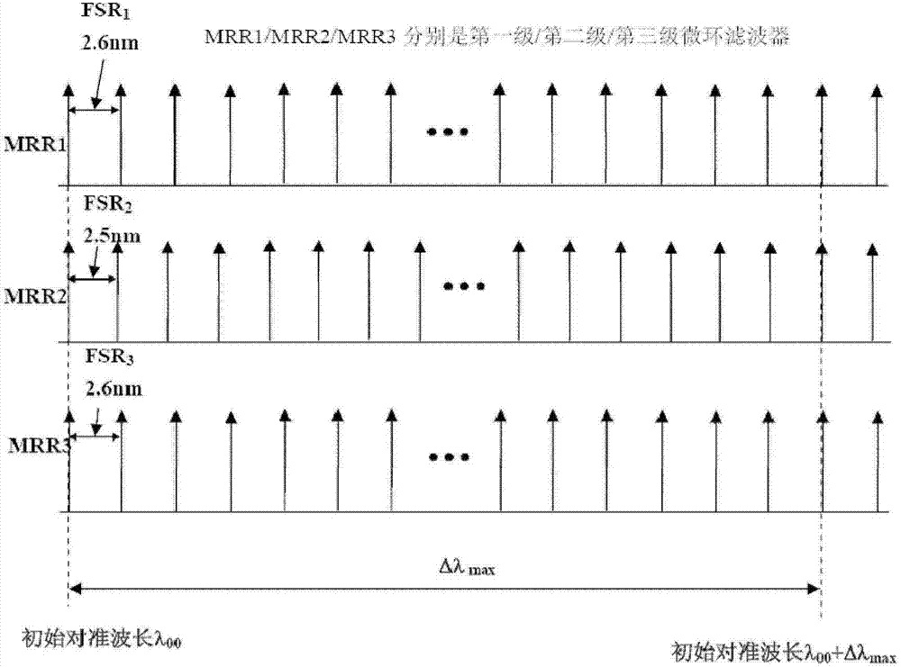
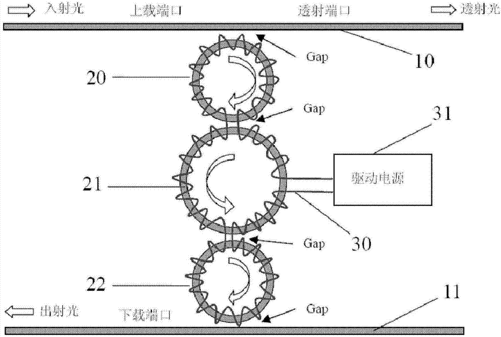
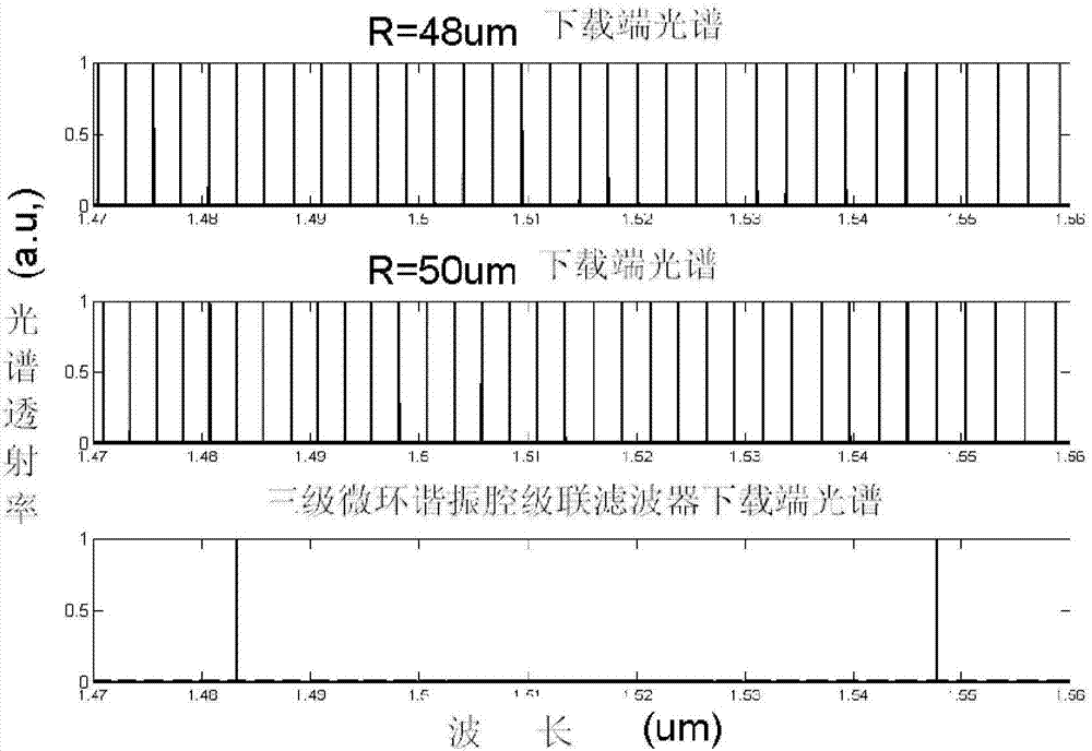
[0027] figure 2 It is the structure and working principle diagram of the thermo-optic tunable three-loop cascade filter with flat-top response and super large free spectral range of the present invention. The thermo-optic tunable three-loop cascade filter includes:

[0028] Single-mode input waveguide 10, the single-mode input waveguide 10 is a common strip waveguide, arranged on one side of the first-stage microring resonator filter 20 in spatial position, and the first-stage microring resonator filter The transverse gap Gap of the ring waveguide is preferably 280 nm, and becomes the input waveguide of the microring resonator 20 through the evanescent field coupling effect of light waves. ;

[0029] The first-stage ra...


PUM

PropertyMeasurementUnit
Radiusaaaaaaaaaa
Radiusaaaaaaaaaa

Abstract

The invention discloses a tunable three-ring cascade filter. The tunable three-ring cascade filter comprises an input waveguide (10) which is the input waveguide of a first-level micro-ring resonant cavity filter (20), the first-level micro-ring resonant cavity filter (20) which is coupled with the input waveguide in the same plane, a second-level micro-ring resonant filter (21) which is coupled with the first-level micro-ring resonant cavity filter in the same plane, a third-level micro-ring resonant cavity filter (22) which is coupled with the second-level micro-ring resonant cavity filter in the same plane, a single-mode output waveguide (11) which is the output waveguide of the third-level micro-ring resonant cavity filter (22), and a heater (30) which is used for heating the first-level micro-ring resonant cavity filter, the second-level micro-ring resonant cavity filter and the third-level micro-ring resonant cavity filter, wherein the radius of the third-level micro-ring resonance cavity filter (22) is equal to the radius of the first-level micro-ring resonant filter.

Description

technical field [0001] The invention relates to the field of integrated optics, in particular to a thermo-optic tunable three-ring cascaded filter with low crosstalk and a large free spectral range. Background technique [0002] In modern optical network technology, a reconfigurable optical add / drop wavelength division multiplexer (ROADM) can flexibly allocate capacity and reconstruct a dense wavelength division multiplexing (DWDM) network, and is a key device for automatic switching of optical networks. Although the FFP filter has been commercialized and can be used to realize low-speed optical network applications, its application is limited because its tuning range is smaller than the EDFA band. Liquid crystal filter has similar performance to FFP, although it has a wider tunable range and faster tuning speed, but it has not been commercially available on a large scale. Due to the reliability problems of MEMS filters, MEMS devices cannot be industrialized in the end. FB...

Claims


Application Information

Patent Timeline
IPC IPC(8): G02F1/01
CPCG02F1/0147
Inventor 任光辉陈少武
Owner INST OF SEMICONDUCTORS - CHINESE ACAD OF SCI
Learn More