
Induction type stamping die and plate positioning device thereof

A technology of positioning device and stamping die, which is applied to positioning device, feeding device, storage device, etc., can solve the problems of large avoidance range, poor pressing effect at the edge of plate blank, irregular processing shape of the avoidance part, etc. The effect of improving the pressing effect, reducing the processing difficulty and narrowing the range of avoidance

Inactive Publication Date: 2015-06-17
ANHUI JIANGHUAI AUTOMOBILE GRP CORP LTD
View PDF8 Cites 3 Cited by
  • Summary
  • Abstract
  • Description
  • Claims
  • Application Information

AI Technical Summary

Problems solved by technology

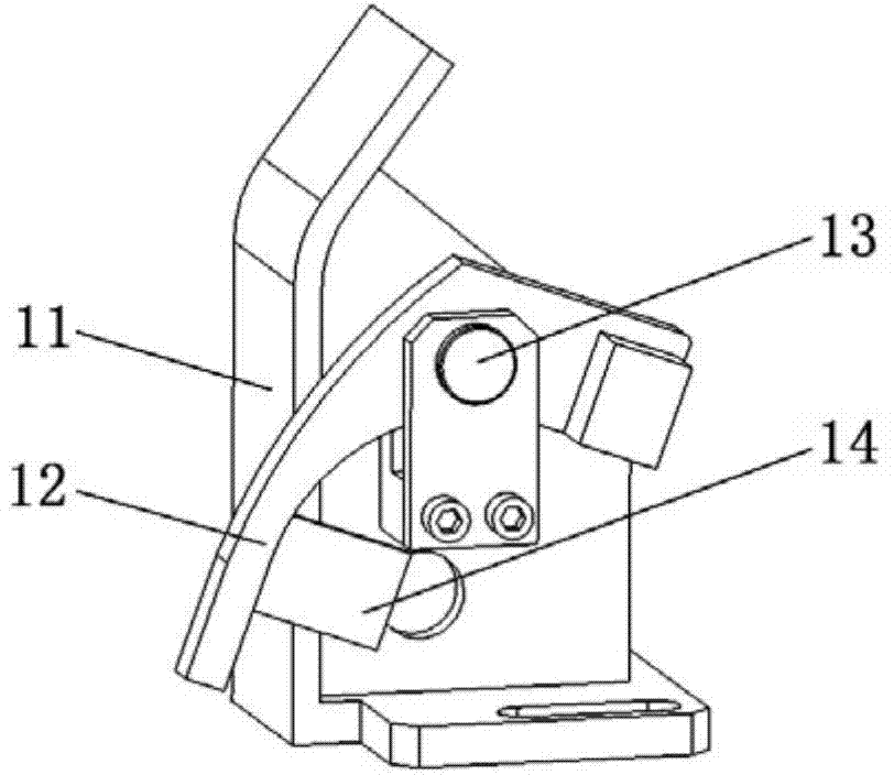
[0005] However, in the above plate positioning device, the movable positioning plate is a cantilever structure with a relatively large rotation radius. After installation, the blank holder and the upper die need to be processed and avoided according to the movement track of the movable positioning plate, resulting in a large avoidance range. , and the processing shape of the avoidance part is irregular, which increases the difficulty of processing; at the same time, due to the excessive processing avoidance of the movable positioning plate, the effect of pressing the material at the edge of the plate blank is also deteriorated

Method used


Image

  • Induction type stamping die and plate positioning device thereof
  • Induction type stamping die and plate positioning device thereof
  • Induction type stamping die and plate positioning device thereof

Examples


Embodiment Construction

[0037] The core of the present invention is to provide a plate positioning device for an induction stamping die, in order to narrow the avoidance range, reduce the processing difficulty of the die avoidance part, and improve the pressing effect of the plate blank. Another core of the present invention is to provide an induction stamping die including the above plate positioning device.

[0038] In order to enable those skilled in the art to better understand the technical solutions of the present invention, the present invention will be further described in detail below in conjunction with the accompanying drawings.

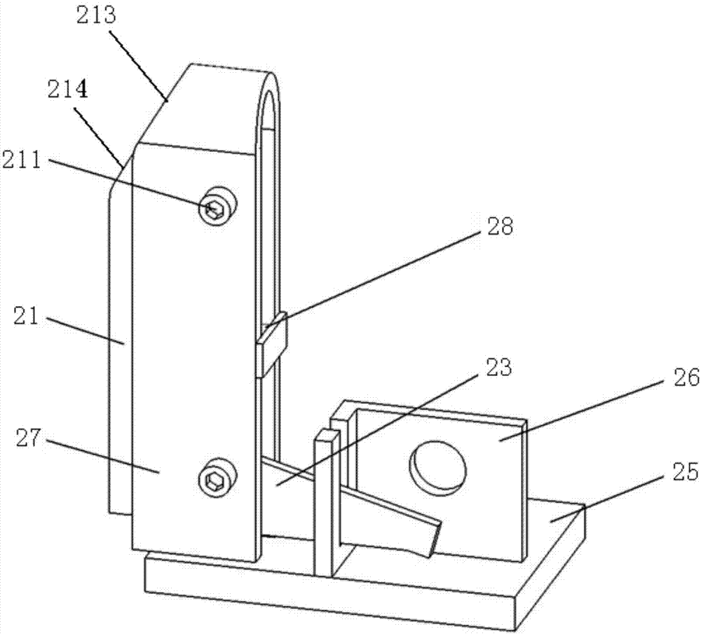
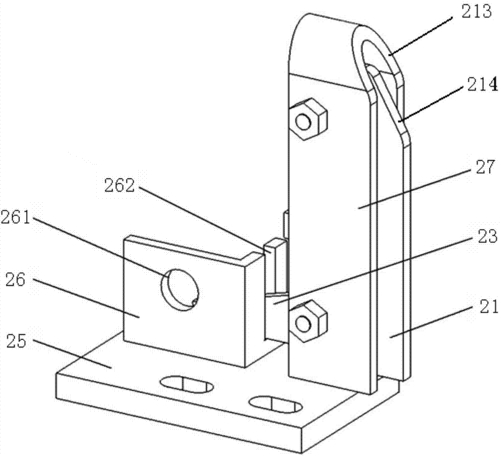
[0039] Such as Figure 2 to Figure 6As shown, in a specific embodiment, the plate positioning device provided by the present invention is used for an induction stamping die, and the plate positioning device includes a support assembly installed on the mold body, a movable positioning assembly installed on the support assembly plate 21, and the induction plate 23...


PUM


Abstract

The invention discloses an induction type stamping die and a plate positioning device thereof. The plate positioning device comprises a supporting assembly installed on a die body, a movable positioning plate installed on the supporting assembly, and an induction plate rotationally installed on the movable positioning plate through a first rotating shaft. The induction plate is matched with a sensor and rotationally installed on the supporting assembly through a second rotating shaft. The movable positioning plate is installed on the supporting assembly in a sliding mode, the sliding direction of the movable positioning plate is close to or away from the direction of the sensor, the first rotating shaft horizontally extends and is perpendicular to the sliding direction of the movable positioning plate, the first rotating shaft is located below the sensor, the induction plate rotates around the second rotating shaft in the vertical plane and inducts or does not induct the sensor. Accordingly, the structure of the movable positioning plate is small, the inward contraction type movement form is adopted, the moving track is small, and therefore the receding range of the die on the movable positioning plate is reduced, the machining difficulty of a die receding part is lowered, and the pressing effect of panel blanks is improved.

Description

technical field [0001] The invention relates to the field of die technology, in particular to a plate positioning device for an induction stamping die. The present invention also relates to an induction stamping die comprising the above plate positioning device. Background technique [0002] In order to improve the accuracy and surface quality of the plate parts, the current automobile stamping parts are mostly processed by automatic production methods, that is, induction stamping dies are used. The induction stamping dies have a plate positioning device. The sensor is triggered and sends a signal to the machine tool to start punching work. [0003] Please refer to figure 1 , figure 1 It is a structural schematic diagram of a typical panel positioning device in the prior art. [0004] Such as figure 1 As shown, the plate positioning device includes a positioning plate 11, a movable positioning plate 12, a rotating shaft 13 and an induction plate 14, wherein the movable ...

Claims


Application Information

Patent Timeline
IPC IPC(8): B21D37/10B21D43/00B21C51/00
CPCB21D37/10B21C51/00B21D43/003
Inventor 陈世涛王海玲何鹏申李辉王法峰黄涛田冰星王震郭奔卢桥
Owner ANHUI JIANGHUAI AUTOMOBILE GRP CORP LTD
Learn More