
Static pressure line double-brake-drum rotary casting device

A spin-casting, double-braking technology, used in manufacturing tools, casting equipment, metal processing equipment, etc., can solve the problems of poor dynamic balance, complex manufacturing process, large cooling temperature difference, etc., to improve the process yield and yield. And, to solve the large difference in machining allowance, to ensure the effect of mixing uniformity

Active Publication Date: 2015-06-10
山东康迈机械有限公司
View PDF8 Cites 2 Cited by
  • Summary
  • Abstract
  • Description
  • Claims
  • Application Information

AI Technical Summary

Problems solved by technology

[0003] Since the inner runners are arranged centripetally, not only will the inner runners be centrally arranged, which is not conducive to the entry of molten iron, but also when the molten iron enters the brake drum molding cavity through the inner runners, the molten iron will be poured into the brake drum molding cavity vertically , and then cause sand washing phenomenon, and the mixing of molten iron is poor; at the same time, with this pouring method, the solidification time of molten iron is not consistent, and the cooling temperature difference between front and back is large, which will not only cause a large difference in hardness of the product, but also cause poor dynamic balance, and then It will lead to large differences in processing allowance; in addition, this pouring method will also affect the process yield and yield
[0004] Moreover, the existing mold must be provided with a riser, the manufacturing process is complicated, and the cost is high

Method used


Image

  • Static pressure line double-brake-drum rotary casting device
  • Static pressure line double-brake-drum rotary casting device
  • Static pressure line double-brake-drum rotary casting device

Examples


Embodiment Construction

[0026] In order to make the object, technical solution and advantages of the present invention clearer, the present invention will be further described in detail below in conjunction with the accompanying drawings and embodiments. It should be understood that the specific embodiments described here are only used to explain the present invention, not to limit the present invention.

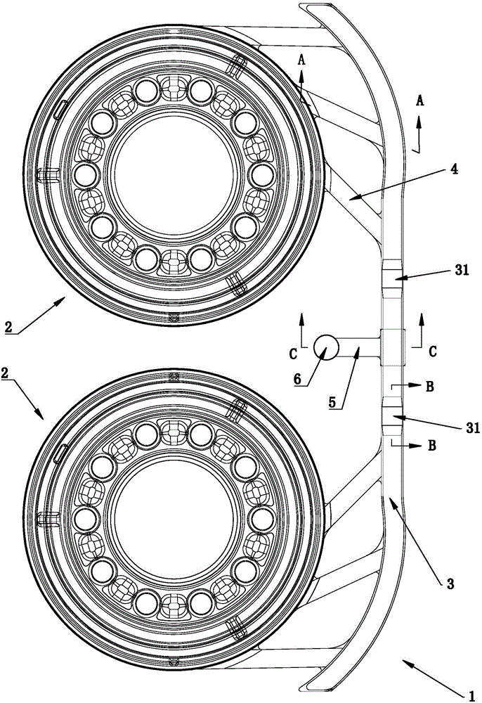
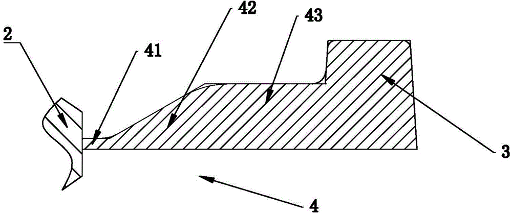
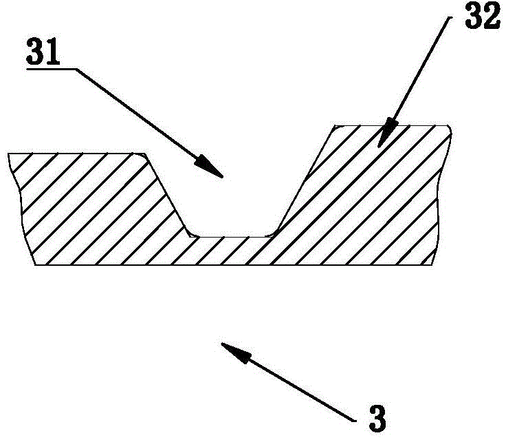
[0027] Such as Figure 1 to Figure 4 Commonly shown, the static pressure line double brake drum rotary pouring device includes a mold body 1 arranged in a sand box, and the mold body 1 includes two brake drum forming molds 2, which are located The first runner forming mold 3 is arranged on the same side, and several inner runner forming molds 4 are arranged on the first runner forming mold 3 corresponding to the two brake drum forming molds 2, and each inner runner The forming dies 4 are all arranged tangentially with the brake drum forming die 2; the several in-runner forming dies 4 arranged tang...


PUM


Abstract

The invention discloses a static pressure line double-brake-drum rotary casting device which comprises a mold body arranged in a sand box. The mold body comprises two brake drum forming molds, wherein a first cross gate forming mold is arranged on the same side of the two brake drum forming molds, and a plurality of ingate forming molds tangent with the brake drum forming molds are arranged on the first cross gate forming mold. A second cross gate forming mold is arranged under the first cross gate forming mold, and a fiber filter screen is arranged between the second cross gate forming mold and the first cross gate forming mold. Two flow choking grooves are formed in the first cross gate forming mold, and a skim bob forming mold is formed between the two flow choking grooves. When molten iron is cast, tangential force is produced and pushes the molten iron to rotate constantly, a sand cut phenomenon is avoided, and mixing uniformity of the molten iron is ensured. The molten iron is cooled and solidifies while casting is completed, the hardness difference of products is reduced, dynamic balance is ensured, the problem of large working allowance difference is solved, and technological yield, rate of finished products and the quality of castings are improved.

Description

technical field [0001] The invention belongs to the technical field of casting, and in particular relates to a static pressure line double brake drum rotary pouring device. Background technique [0002] At this stage, the molds for casting double brake drums generally include: brake drum forming dies and runner forming dies. There are several inner runner forming dies between the runner forming dies and brake drum forming dies. The inner runner forming molds are all facing the center of the brake drum forming mold (that is, the center line of each inner runner forming mold passes through the center of the brake drum forming mold, which can also be called: the inner runner forming mold is set centripetally) , so that in the casting production, after the mold is placed in the sand box and the sand mold is formed by the sand shooting process, the mold is taken out, the brake drum molding cavity is formed at the brake drum molding mold position, and the runner molding mold is fo...

Claims


Application Information

Patent Timeline
Patent Type & Authority Applications(China)
IPC IPC(8): B22C9/28B22C9/08
CPCB22C9/082B22C9/20B22C9/28
Inventor 袁超韩维波巨勐利刘玉宝弭希凯
Owner 山东康迈机械有限公司
Learn More