Eureka AIR delivers breakthrough ideas for toughest innovation challenges, trusted by R&D personnel around the world.

Image information detecting method

A detection method and technology of image information, applied in measurement devices, material analysis by optical means, instruments, etc., can solve the problems of large workload, misjudgment, and reduced efficiency of correction algorithms, and achieve improved search efficiency and accurate positioning. Results, the effect of overcoming the positioning bias

Inactive Publication Date: 2015-06-03
MINGSHUO COMP (SUZHOU) CO LTD +1
View PDF6 Cites 4 Cited by
  • Summary
  • Abstract
  • Description
  • Claims
  • Application Information

AI Technical Summary

Problems solved by technology

Furthermore, when automatic optical inspection is used for product inspection on the production line, the image on the product becomes a dynamic image. Therefore, mechanical positioning, manual positioning, and comparison and positioning of pattern elements are required, which slows down the inspection speed and reduces the Productivity
Under the limitations of existing technology, problems such as large errors, frequent occurrence of offsets, and large workload of correction algorithms will easily occur, which will lead to reduced efficiency and positioning deviation, which will cause risks and errors in subsequent detection and identification. sentence

Method used


Image

  • Image information detecting method
  • Image information detecting method
  • Image information detecting method

Examples


Embodiment Construction

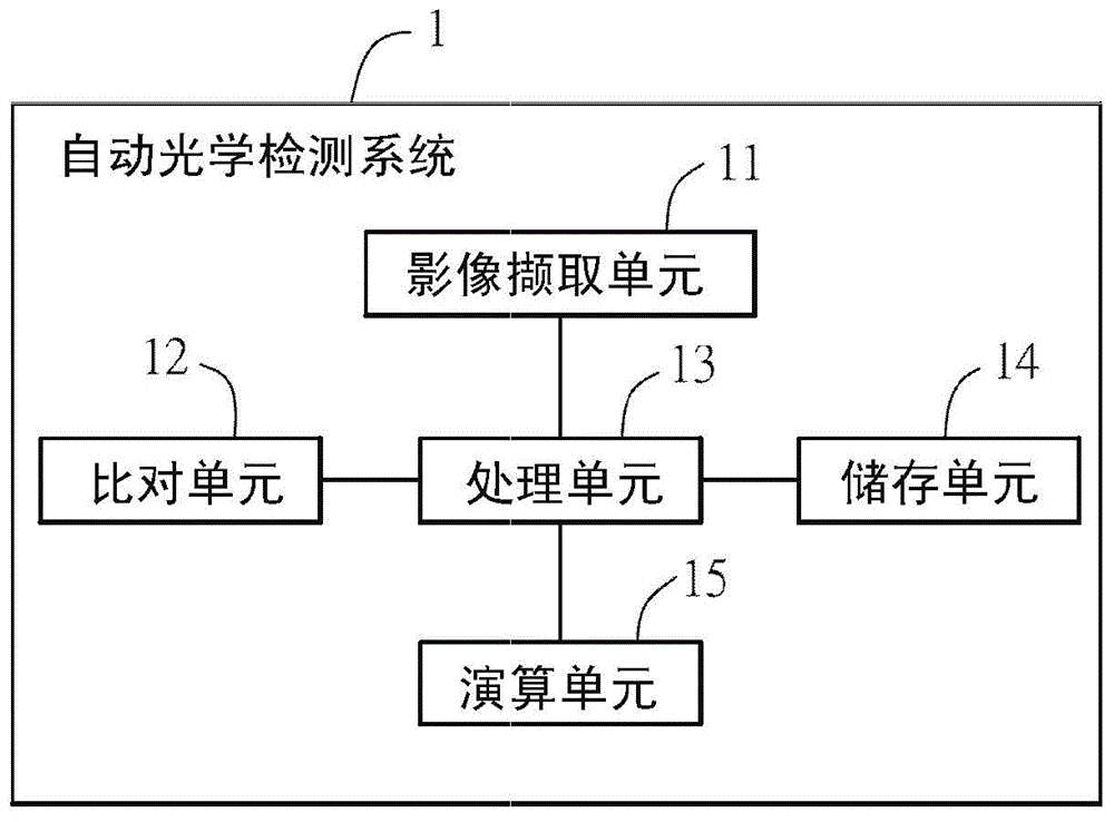
[0036] An image information detection method (hereinafter referred to as the detection method) according to a preferred embodiment of the present invention will be described below with reference to related drawings, which is applied to automatic optical detection, wherein the same components will be described with the same reference symbols.

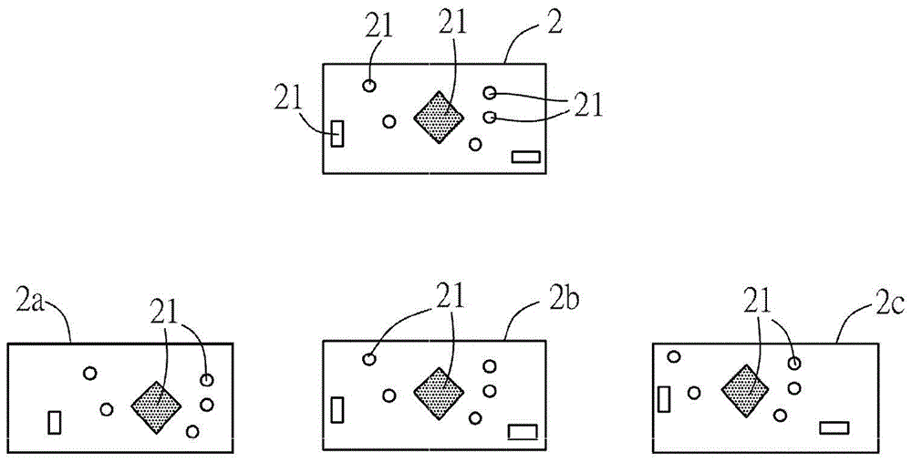
[0037] figure 1 It is a flow chart of the steps of an image information detection method in a preferred embodiment of the present invention, please refer to figure 1 As shown, the image information detection method of the present invention includes the following steps: selecting a matching data from a standard sample (S11); capturing a continuous image of a sample to be tested (S13); obtaining several frames of images to be tested from the continuous image (S15); selecting a characteristic data of each image to be tested (S17); and comparing the matching data and each characteristic data to obtain a matching rate (S19).

[0038] It shou...


PUM


Abstract

The invention discloses an image information detecting method. The image information detecting method comprises the following steps: selecting a matched datum from a standard sample; capturing a continuous image of a to-be-detected sample; acquiring a plurality of frame to-be-detected images from the continuous image; selecting a character datum of each to-be-detected image; and comparing the matched datum with each character datum so as to obtain a matched rate. By utilizing the image information detecting method, the positioning precision can be improved so as to reduce the detection deviation.

Description

technical field [0001] The invention relates to a method for detecting image information. Background technique [0002] With the development of high-resolution, the improvement of process technology and the demand for automation in industrial production, the traditional manual visual inspection (Manual Visual Inspection, MVI) detection method has gradually become limited. Usually, it can only detect missing components, model classification, and some obvious mistakes. Because it is easily affected by human subjective and objective factors, it has high instability, difficulty and cost. Therefore, the invention of Automated Optical Inspection (AOI) equipment came into being. [0003] Automatic optical inspection is a detection method with considerable market potential in recent years. Its basic working principle is mainly to obtain the graphic information of the detected object through the image sensor, and then use the built-in computer software to process and calculate for ...

Claims


Application Information

Patent Timeline
Patent Type & Authority Applications(China)
IPC IPC(8): G01N21/84
Inventor 许彬阳艳杨世扬王春香
Owner MINGSHUO COMP (SUZHOU) CO LTD
Why Eureka
Eureka Blog
Learn More