Sludge anoxic and intensified fermentative hydrolysis of multi-format a 2 oSystem and its application

A sludge anoxic, multi-format technology, applied in water/sewage multi-stage treatment, water/sludge/sewage treatment, chemical instruments and methods, etc. The problem of low carbon source content, etc., can achieve better biological nitrogen removal effect, improve precipitation state, and improve biological phosphorus removal effect.

Active Publication Date: 2017-02-01
THUNIP CORP LTD
View PDF7 Cites 2 Cited by
  • Summary
  • Abstract
  • Description
  • Claims
  • Application Information

AI Technical Summary

Problems solved by technology

However, the carbon source content of many urban sewage is low, and there are many macromolecular organic matter or non-degradable organic matter in the carbon source, which cannot meet the needs of nitrogen and phosphorus removal for high-quality carbon sources.

Method used


Image

  • Sludge anoxic and intensified fermentative hydrolysis of multi-format a  <sup>2</sup> oSystem and its application
  • Sludge anoxic and intensified fermentative hydrolysis of multi-format a  <sup>2</sup> oSystem and its application
  • Sludge anoxic and intensified fermentative hydrolysis of multi-format a  <sup>2</sup> oSystem and its application

Examples


Embodiment 1

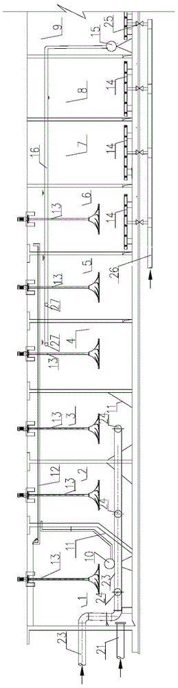
[0044] See figure 1 , a sludge anoxic and enhanced fermentative hydrolysis of multi-format A 2 O system, the sewage enters the system through the water inlet pipe 23, the multi-format A 2 O system includes sludge anoxic grid 1, 1# enhanced fermentation hydrolysis grid 2, 2# enhanced fermentation hydrolysis grid 3, 1# anoxic grid 4, 2# anoxic grid 5, transition grid 6, 1# aerobic grid 7 , 2# aerobic grid 8, 3# aerobic grid 9, and secondary settling tank 22.

[0045] The sludge anoxic grid 1 and the enhanced fermentation hydrolysis grid, the anoxic grid, the transition grid and the aerobic grid are arranged in sequence, and are separated from each other by a partition wall; the aerobic grid is connected to the secondary settling tank 22 through pipelines; The return sludge pipeline 21 is connected to the sludge anoxic grid 1, and the aerobic grid is connected to the anoxic grid through the internal return pipeline 16 and the internal return sludge pump 15; the supernatant liqu...

Embodiment 2

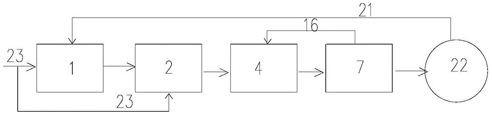
[0052] image 3 It is a flow chart of the system biochemical treatment process proposed by the present invention. image 3 Only 2 (1# enhanced fermentation and hydrolysis grid), 4 (1# anoxic grid), and 7 (1# aerobic grid) are shown in , indicating that the sewage is in the sludge anoxic grid, enhanced fermentation and hydrolysis grid, anoxic grid, Flow between aerobic grids. The method that the system of application embodiment 1 carries out sewage treatment is:

[0053] The sewage enters the system through the water inlet pipe, and all the sewage enters the enhanced fermentation and hydrolysis grid. The hydraulic retention time in the enhanced fermentation and hydrolysis grid is 2 hours, enters the anoxic grid, and then enters the transition grid.

[0054] The last grid of the aerobic grid is equipped with an internal reflux pump to return the mixed solution to the 5 (2# anoxic grid) anoxic grid. There is an internal reflux mixed liquid point 27 in the anoxic grid, and the r...


PUM


Abstract

The invention provides a multi-cell A<2>O system of sludge anoxic and strengthened fermentation hydrolysis. The system comprises a sludge anoxic cell, a strengthened fermentation hydrolysis cell, an anoxic cell, an aerobic cell and a secondary sedimentation tank, wherein a water inlet pipe is connected with the sludge anoxic cell; the aerobic cell is connected with the anoxic cell through an internal reflux pipeline; and 2 or 3 strengthened fermentation hydrolysis cells, 2 or 3 anoxic cells and 2-4 aerobic cells are provided. By adopting the system provided by the invention, the sludge of the sludge anoxic cell is denitrified through endogenous respiration, and the internal carbon source in sludge is fully used so that more carbon sources are applied to a nitrogen and phosphorus removal biological reaction of the mainstream AAO technology; the nitrate content of the sludge anoxic cell can be reduced to 0, the redox potential in the strengthened fermentation hydrolysis cell is very low, and the effect of anaerobic phosphorus release is improved; and meanwhile, hydrolysis fermentation is performed through a high-concentration sludge layer in the strengthened fermentation hydrolysis cell, macromolecular or refractory organic substances in the inflow water are converted into low-molecular-weight fatty acid, and a high-quality carbon source is provided for the anaerobic phosphorus release and anoxic denitrification reactions.

Description

technical field [0001] The invention relates to a multi-format A of sludge anoxic-enhanced fermentation hydrolysis 2 The O process belongs to the technical field of sewage treatment. Background technique [0002] A 2 The O process is an existing process for simultaneously removing nitrogen and phosphorus. The advantage of this process is that the process flow is simple, but there are also inherent defects, mainly in the organic load, sludge age, etc. There are contradictions and competitions in the demand for carbon sources and carbon sources, and it is difficult to obtain efficient removal of nitrogen and phosphorus in the same system at the same time. [0003] Traditional A 2 The return sludge from the secondary settling tank of O process enters A at a ratio of 100%. 2 In the anaerobic section of the O pool, a large amount of nitrate and a small amount of DO (dissolved oxygen, dissolved oxygen) carried in the return sludge enter the anaerobic section. However, only wh...

Claims


Application Information

Patent Timeline
Patent Type & Authority Patents(China)
IPC IPC(8): C02F9/14
Inventor 周丽颖李星文王旭王晗凌薇
Owner THUNIP CORP LTD
Why Eureka
Try Eureka