Method and device applied to heating influent by virtue of efficient anaerobic reactor

An anaerobic reactor, high-efficiency technology, applied in chemical instruments and methods, anaerobic digestion treatment, energy wastewater treatment, etc., can solve the problems of polluted environment, unable to guarantee stable temperature of mesophilic anaerobic fermentation, energy reduction, etc., and achieve reduction The effects of environmental pollution, promotion of sustainable development, and reduction of energy consumption

Inactive Publication Date: 2015-06-03
山东绿泉环保科技股份有限公司
View PDF4 Cites 12 Cited by
  • Summary
  • Abstract
  • Description
  • Claims
  • Application Information

AI Technical Summary

Problems solved by technology

[0004] However, in the northern region, due to the cold weather in winter and the low outdoor temperature, the stable temperature required for mesophilic anaerobic fermentation cannot be guaranteed if general warming and heat preservation measures are not taken for the anaerobic reactor.
At present, most of the heat energy required by anaerobic reactors is supplied by combustion of coal, oil or natural gas, which will inevitably lead to energy reduction and environmental pollution.

Method used


Image

  • Method and device applied to heating influent by virtue of efficient anaerobic reactor
  • Method and device applied to heating influent by virtue of efficient anaerobic reactor
  • Method and device applied to heating influent by virtue of efficient anaerobic reactor

Examples


Embodiment

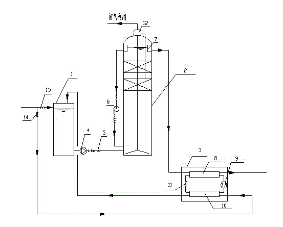
[0025] Embodiment: A method and device for heating the inlet water of a high-efficiency anaerobic reactor. The structure can refer to the accompanying drawings, and mainly includes a feed tank 1, a high-efficiency anaerobic reactor 2 and a heat pump unit 3. The heat pump unit 3 is composed of an evaporator 8 , a compressor 9 , a condenser 10 , an expansion valve 11 and gate valves 13 and 14 .

[0026] The feed tank 1, the high-efficiency anaerobic reactor 2 and the heat pump unit 3 are connected in sequence.

[0027] The heat pump unit 3 is composed of four devices: an evaporator 8 , a compressor 9 , a condenser 10 and an expansion valve 11 , which are connected to each other through refrigerant pipelines to form a closed circulation system.

[0028] The water inlet pipe of the feed tank 1 is connected to the water inlet of the condenser 10, the water outlet of the condenser 10 is connected to the feed tank 1 through a pipeline, and the water outlet system 7 of the high-effici...

experiment example

[0037] EXPERIMENTAL EXAMPLE An experiment was carried out using a method and device for heating the feed water of a high-efficiency anaerobic reactor described in the embodiment.

[0038] The amount of wastewater treated in this experiment is 5000m 3 / d, the inlet water temperature of the feed pool in cold regions is 15°C in winter, and the temperature of the heated anaerobic feed pool is 32°C (the heating season is calculated as 5 months), the temperature required for subsequent aerobic treatment at 23°C (the efficiency of the boiler is 20%, the efficiency of coal combustion is 70%, and the heat capacity of water is 4.2×10³ J / (kg·℃), the calorific value of coal is 3.0×10 7 J / kg).
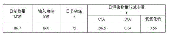
[0039] The design values ​​of the heat pump unit are shown in the table below:

[0040]

[0041] The heating efficiency (COP) of the heat pump unit is taken as 4.2, and the experimental results obtained are shown in the following table:

[0042]

[0043] In the heating season, compared wit...


PUM


Abstract

The invention provides a method and a device applied to heating influent by virtue of an efficient anaerobic reactor. The device mainly comprises a material inlet pool, the efficient anaerobic reactor and a heat pump unit, wherein the material inlet pool, the efficient anaerobic reactor and the heat pump unit are connected with one another sequentially; the heat pump unit consists of an evaporator, a compressor, a condenser and an expansion valve, and the evaporator, the compressor, the condenser and the expansion valve are connected with one another by virtue of a refrigerant pipeline to form a closed circulation system; a water inlet pipe of the material inlet pool is connected with a water inlet of the condenser, a water outlet of the condenser is connected with the material inlet pool by virtue of a pipeline, and a water outlet system of the efficient anaerobic reactor is connected with the evaporator by virtue of a pipeline. The method and the device have the beneficial effects of 1, remarkable environmental protection benefit; 2, energy saving, and consumption lowering; 3, economy and reliability in running; and 4, good social benefit.

Description

technical field [0001] The invention belongs to the field of energy saving and environmental protection, and in particular relates to a method and a device for heating the inlet water of a high-efficiency anaerobic reactor. Background technique [0002] Energy and environment are two major themes of sustainable development. Since the beginning of the new century, with the growth of population, the improvement of economic level and the progress of society, the energy crisis has been deepening, and the pollution and destruction of the ecological environment have also been intensified. With global energy consumption growing at a rate of 5% per year, fossil fuels are expected to last for one to two hundred years, and the world's energy situation is grim. my country's per capita energy is poor, and the per capita possession is only 1 / 2 of the world average and 1 / 10 of the United States. With the rapid development of the economy, the problem of energy shortage is becoming more a...

Claims


Application Information

Patent Timeline
IPC IPC(8): C02F3/28
CPCY02W10/30C02F3/28C02F2209/02C02F2301/10
Inventor 周焕祥宗可卿房爱东张金华汪艳雯
Owner 山东绿泉环保科技股份有限公司
Why Eureka
Try Eureka