Energy-saving control device for AC electric welding machine

A technology of energy-saving control and alternating current, applied in auxiliary devices, arc welding equipment, manufacturing tools, etc., can solve problems such as difficult to achieve, difficult to popularize, and inflexible to use, so as to improve the average power factor, facilitate production and popularization, The effect of reducing the production cost

Inactive Publication Date: 2015-06-03
CHENGDU XIONGGU JIASHI ELECTRICAL
View PDF0 Cites 1 Cited by
  • Summary
  • Abstract
  • Description
  • Claims
  • Application Information

AI Technical Summary

Problems solved by technology

[0002] AC welding machine is a commonly used low-voltage electrical equipment. It is most widely used in construction, metallurgy, machinery manufacturing and other industries. It is mainly used for welding steel materials. Its disadvantages are frequent intermittent working hours and long no-load running time. Usually, when welding, the lead wire of the electric welding machine is long, and the operating point is far away from the power supply. Especially in the high-altitude operation during construction welding, it is difficult to disconnect the power supply when the welding machine is unloaded.
At the same time, the high-tech electric welding machines controlled by electronic circuits that have appeared in recent years have a good power-saving effect, but they are inconvenient to carry, inflexible to use, have strict requirements on the working environment, and are expensive and difficult to promote.

Method used


Image

  • Energy-saving control device for AC electric welding machine

Examples


Embodiment Construction

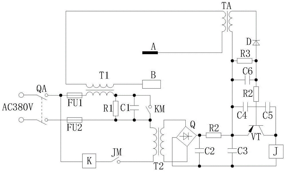
[0009] The present invention will be further described below in conjunction with accompanying drawing:

[0010] like figure 1 Shown: the present invention includes a power switch QA, a first fuse resistor FU1, a second fuse resistor FU2, a current transformer TA, an AC contactor K, a welding transformer T1, a transformer T2, a first capacitor C1, and a second capacitor C2 , third capacitor C3, fourth capacitor C4, fifth capacitor C5, sixth capacitor C6, first resistor R1, second resistor R2, third resistor R3, rectifier Q, transistor VT, diode D and relay J, welding transformer The first end of the primary coil of T1 is connected to the live wire of the AC power supply, and the second end of the primary coil of the welding transformer T1 is simultaneously connected to the first end of the first resistor R1, the first end of the first capacitor C1 and the normally open contact switch of the AC contactor The first end of KM is connected, and the second end of the first resistor...


PUM


Abstract

The invention discloses an energy-saving control device for an AC electric welding machine. The device comprises a power switch, a first fuse resistor, a second fuse resistor, a current transformer, an AC contactor, a welding transformer, a transformer, a first capacitor, a second capacitor, a third capacitor, a fourth capacitor, a fifth capacitor, a sixth capacitor, a first resistor, a second resistor, a third resistor, a rectifier, a triode, a diode and a relay. With the adoption of the device, a power supply can be automatically delayed to be cut off in case that the electric welding machine is in idle load, and the power supply can be automatically started during welding; when the power supply is automatically delayed to be cut off, the frequent action of the electric welding machine during stopping welding within a short time can be effectively prevented, and therefore, the idle load loss can be reduced, and the average power factors can be increased; in addition, the device has the advantages of being low in power consumption, convenient to operate, high in sensitivity and high in practicability; few elements are used, so that the cost is low, the manufacturing cost is reduced, and the production and popularization are easily carried out.

Description

technical field [0001] The invention relates to an auxiliary device for an electric welding machine, in particular to an energy-saving control device for an AC electric welding machine. Background technique [0002] AC welding machine is a commonly used low-voltage electrical equipment. It is most widely used in construction, metallurgy, machinery manufacturing and other industries. It is mainly used for welding steel materials. Its disadvantages are frequent intermittent working hours and long no-load running time. Usually, when welding, the lead wire of the electric welding machine is long, and the operating point is far away from the power supply. Especially for high-altitude operations during construction welding, it is difficult to disconnect the power supply when the welding machine is unloaded. At the same time, the high-tech electric welding machines controlled by electronic circuits that have appeared in recent years have good power-saving effects, but they are inco...

Claims


Application Information

Patent Timeline
Patent Type & Authority Applications(China)
IPC IPC(8): B23K37/00
CPCB23K9/1043B23K9/105
Inventor 李堂权王安涛万绍梁邱文虎刘碧清何江龙
Owner CHENGDU XIONGGU JIASHI ELECTRICAL
Why Eureka
Try Eureka