Full-hardware type signal lamp coding circuit

A coding circuit and signal light technology, applied in the direction of pulse duration/width modulation, etc., can solve the problems of high production cost and high software management cost, and achieve the effects of low production cost, no need for software management, and convenient adjustment

Inactive Publication Date: 2015-05-27
GUIZHOU HUAYANG ELECTRICAL
View PDF3 Cites 0 Cited by
  • Summary
  • Abstract
  • Description
  • Claims
  • Application Information

AI Technical Summary

Problems solved by technology

[0002] In the light information communication system of traditional aircraft, ships, and chariots, because of the diversification of information, the light control circuit is mostly controlled by software. The disadvantage is: high production cost, and the software management cost is also high in military systems.

Method used


Image

  • Full-hardware type signal lamp coding circuit

Examples


Embodiment Construction

[0041] The specific implementation, features and functions of the all-hardware signal light encoding circuit according to the present invention will be described in detail below in conjunction with the accompanying drawings and preferred embodiments.

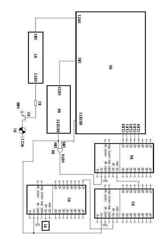
[0042] An all-hardware signal light encoding circuit of the present invention consists of a crystal oscillator U1, an 8-bit counter U2, an 8-bit counter U3, an 8-bit counter U4, a logic control circuit U5, a mode control circuit U6, a pulse width control circuit U7, a dual-input single Output AND gate U8, resistor R1, signal light D1, NPN transistor D2, power supply VCC, signal light power VCC1, signal light power ground GND;

[0043] The output terminal of the crystal oscillator U1 is connected to the input terminal CLK UP of the 8-bit counter U2, the output terminal Q7 of the 8-bit counter U2 is connected to the input terminal CLK UP of the 8-bit counter U3, and the output terminal Q4 of the 8-bit counter U3 is connected to the...


PUM


Abstract

The invention discloses a full-hardware type signal lamp coding circuit. The full-hardware type signal lamp coding circuit is characterized by comprising a crystal oscillator U1, an 8-bit counter U2, an 8-bit counter U3, an 8-bit counter U4, a logic control circuit U5, a mode control circuit U6, a pulse width control circuit U7, a dual-input single-output and gate U8, a resistor R1, a signal lamp D1, an NPN triode D2, a power supply VCC, a signal lamp power supply VCC1 and a signal power supply ground GND, wherein the crystal oscillator U1, the 8-bit counter U2, the 8-bit counter U3 and the 8-bit counter U4 are matched with the mode control circuit U6 to produce a required time unit, the logic control circuit U5 is used for producing required high and low level signals with a specific law so as to control a twinkling law of the signal lamp and express different information, and the pulse width control circuit U7 for twinkling of the signal lamp is used for controlling light-emitting time width during twinkling of the signal lamp. The full-hardware type signal lamp coding circuit disclosed by the invention can obtain different information codes and increase and decrease the number of modes, and has the advantages of low cost, stable and reliable circuit and reliable performances.

Description

technical field [0001] The invention relates to a light information exchange system for aircraft, ships, etc., and specifically relates to a full-hardware signal light encoding circuit for realizing the exchange of light information required by aircraft, ships, and chariots. Background technique [0002] In traditional aircraft, ships, and tank lighting information exchange systems, because of the diversity of information, the lighting control circuits are mostly controlled by software. The disadvantages are: high production costs, and high software management costs in military systems. Contents of the invention [0003] The object of the present invention is to overcome above-mentioned shortcoming and provide a kind of all-hardware signal lamp coding circuit that can obtain different information coding and increase, reduce mode number, cost is low, circuit is stable and reliable, and performance is reliable. [0004] Purpose of the present invention and its main technical...

Claims


Application Information

Patent Timeline
Patent Type & Authority Applications(China)
IPC IPC(8): H03K7/08
Inventor 龙胜玺
Owner GUIZHOU HUAYANG ELECTRICAL
Why Eureka
Try Eureka