
A Fixed Swing High Drive Local Oscillator Waveform Buffer

A fixed swing, buffer technology, applied in the direction of differential amplifiers, DC-coupled DC amplifiers, etc., to achieve the effect of strong driving ability

Active Publication Date: 2017-09-15
SOUTHEAST UNIV
View PDF5 Cites 0 Cited by
  • Summary
  • Abstract
  • Description
  • Claims
  • Application Information

AI Technical Summary

Problems solved by technology

However, since the NMOS transistor and PMOS transistor adopt a uniform bias voltage, the input signal swing must be large enough to make the switching process more thorough and rapid

Method used


Image

  • A Fixed Swing High Drive Local Oscillator Waveform Buffer
  • A Fixed Swing High Drive Local Oscillator Waveform Buffer
  • A Fixed Swing High Drive Local Oscillator Waveform Buffer

Examples


Embodiment Construction

[0031] The present invention will be further explained below in conjunction with the accompanying drawings.

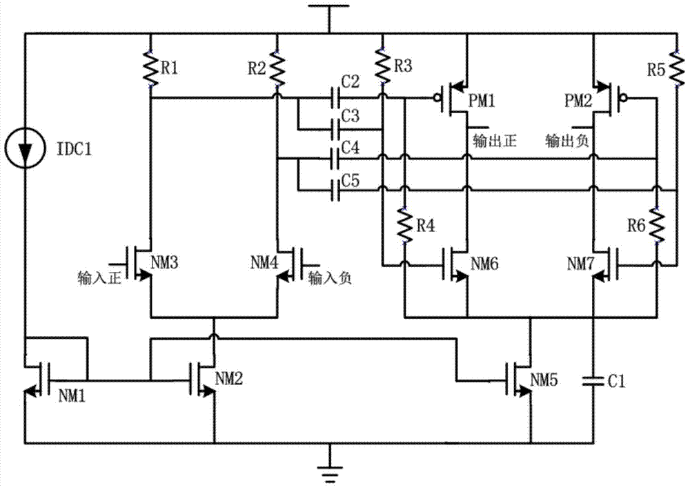
[0032] A fixed-swing high-drive local oscillator waveform buffer, the entire buffer includes a differential pre-amplifier using a resistive load and a self-biased CMOS buffer structure; a bias circuit of the self-biased CMOS buffer structure is controlled by a tail current source.

[0033] The differential amplifier is used to provide the pre-amplification function; the self-biased CMOS buffer structure is based on the traditional CMOS buffer structure. A self-biased circuit is designed to bias the NMOS and PMOS transistors at the upper and lower boundaries of the output swing, respectively. The drive capability of this buffer with limited input swing is enhanced. And because of the self-biasing method, the bias circuit is omitted. The entire buffer is controlled by a tail current source to control the bias current, and a filter capacitor is connected in parallel betw...


PUM


Abstract

A fixed-swing high-drive local oscillator waveform buffer, comprising a first-stage pre-amplifier circuit and a buffer-stage circuit with fixed output swing and high drive capability; the buffer circuit is a complementary structure, wherein the amplifier tube is self-biased Compared with the traditional buffer structure based on resistive load differential amplifier and CMOS inverter, the local oscillator waveform buffer of the present invention has stronger driving ability , which can achieve a steeper LO waveform and a fixed signal swing.

Description

technical field [0001] The invention relates to the technical field of waveform buffers, in particular to a fixed-swing high-drive local oscillator waveform buffer. Background technique [0002] In the radio frequency transceiver circuit, the local oscillator buffer circuit is used to connect the frequency synthesizer and the mixer, amplify and match the local oscillator signal output by the frequency synthesizer to the swing required by the mixer. At the same time, due to the existence of the grid capacitance of the local oscillator switching tube of the mixer, the buffer must have a strong driving capability. [0003] There are two main types of traditional LO buffer structures: [0004] A simple resistive load differential amplifier structure, the buffer based on this structure is usually composed of two or three such differential amplifier cascades; the pre-amplifier is responsible for pre-amplifying the swing of the signal, so that the last stage In the state of satur...

Claims


Application Information

Patent Timeline
Patent Type & Authority Patents(China)
IPC IPC(8): H03F3/45
Inventor 陈超吴建辉黄成李红田茜
Owner SOUTHEAST UNIV
Learn More