
Seismic horizon calibration method utilizing vertical seismic profiling (VSP) and well-logging combination

A horizon calibration and well logging technology, applied in the field of seismic exploration data interpretation, can solve problems such as unsatisfactory reservoir calibration, time-consuming, inconsistent polarity, etc.

Active Publication Date: 2015-05-27
BC P INC CHINA NAT PETROLEUM CORP +1
View PDF3 Cites 34 Cited by
  • Summary
  • Abstract
  • Description
  • Claims
  • Application Information

AI Technical Summary

Problems solved by technology

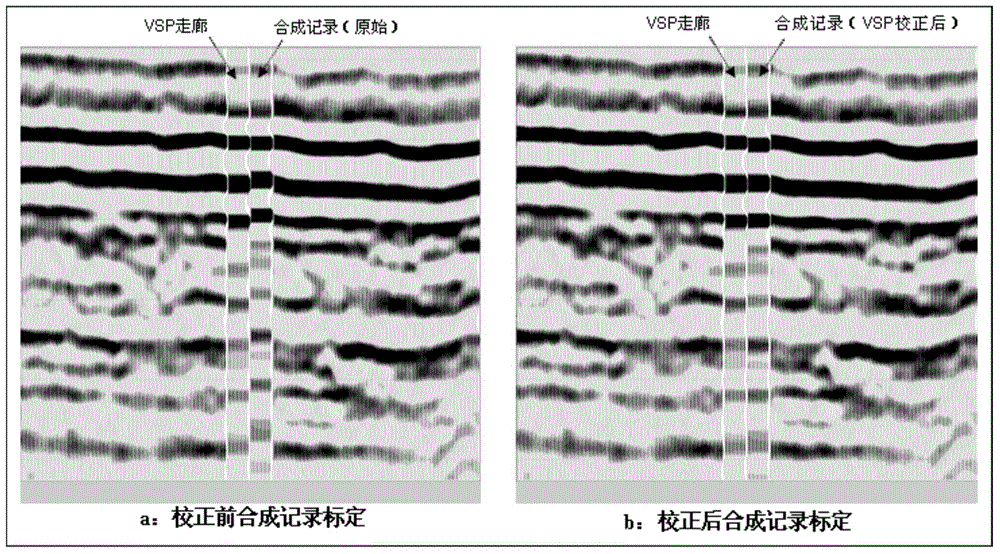
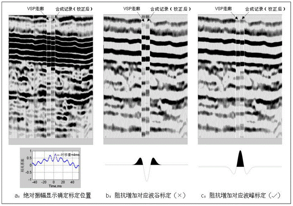
However, the VSP horizon calibration also has the following problems: (1) The VSP velocity is the average velocity of the formation, and the stacking velocity of the seismic data is the equivalent velocity, and the corresponding time waveforms of the two are inconsistent; (2) The VSP logging detector is placed in the well , there is no half-wave loss, but the ground geophone is buried on the ground and is located on the half-space interface of the elastic medium, so there is a half-wave loss, which causes the polarity of the two to be inconsistent (the VSP corridor superposition section is a negative polarity section); (3 ) The short-range multiple waves enhance the energy of the downlink pulse observed by the VSP, which will delay the arrival time of the main energy of the pulse
[0008] VSP bridge calibration can link the seismic time with the geological depth, but the current bridge calibration method is mainly manual. This manual calibration has a certain accuracy and is time-consuming. At the same time, the observation point distance of VSP is relatively large. is 5m or 10m, and the distance between the obtained time-depth pairs is 5m or 10m. Such accuracy cannot satisfy fine reservoir calibration

Method used


Image

  • Seismic horizon calibration method utilizing vertical seismic profiling (VSP) and well-logging combination
  • Seismic horizon calibration method utilizing vertical seismic profiling (VSP) and well-logging combination
  • Seismic horizon calibration method utilizing vertical seismic profiling (VSP) and well-logging combination

Examples


Embodiment Construction

[0064] The specific implementation steps of the present invention are as follows:

[0065] 1) VSP measures and obtains the P-wave time-depth relationship (H i , T vsp,i );

[0066] 2) According to the zero well source distance data, the corridor stacking section is obtained through true amplitude restoration, zero phase deconvolution, wave field separation, corridor cutting and stacking processing;

[0067] 3) Log and obtain acoustic logging and density logging data; if there is no density logging curve, use Gardner empirical formula to obtain density data, Gardner empirical formula is: ρ=0.31·ν 0.25 .

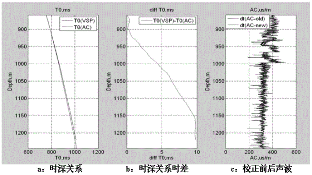
[0068] 4) Calculate the time-depth relationship of the sound wave (H i , T AC,i ), calculate the time difference with the time-depth relationship of VSP, and then correct the acoustic wave curve ( figure 1 ); Calculate the time-depth relationship of the sound wave (H i , T AC,i ) formula is:

[0069] T AC , ...


PUM


Abstract

The invention relates to a seismic horizon calibration method utilizing a vertical seismic profiling (VSP) and well-logging combination. The seismic horizon calibration method comprises the following steps: measuring and obtaining a longitudinal wave time-depth relationship and a corridor stacking profile according to zero offset data, performing well logging and obtaining acoustic well logging and density well logging data, calculating an acoustic wave time-depth relationship and a VSP time-depth relationship to get time difference, correcting an acoustic wave curve, obtaining a synthetic record through corrected well-logging curve and seismic wavelet convolution, making a horizon calibration chart after the time shift quantity of a VSP corridor and the correct polarity are determined and performing horizon calibration on a ground seismic profile according to known drilling geological stratification. According to the seismic horizon calibration method, the acoustic well logging error and the frequency dispersion effect are eliminated, the synthetic record making precision is improved, human factors in the calibration are reduced, and the calibration accuracy is improved.

Description

technical field [0001] The invention belongs to the field of seismic exploration data interpretation, and in particular relates to a method for calibrating seismic horizons in combination with vertical seismic profile VSP (Vertical Seismic Profiling) and well logging. Background technique [0002] Seismic exploration is an exploration method that artificially induces crustal vibrations and describes the underground geological conditions. Conventional seismic exploration arranges excitation points near the surface, and the excitation produces seismic waves that propagate downward and reflect upward after encountering a reflective layer. Geophones are placed on the ground to receive the reflected waves from the underground interface. This seismic exploration method obtains the geological information of the reflection interface, which is finally displayed in the form of events on the seismic section. It only has the concept of time domain and lacks the concept of depth domain. ...

Claims


Application Information

Patent Timeline
IPC IPC(8): G01V1/40
Inventor 陈沅忠李彦鹏赵海英杜金玲
Owner BC P INC CHINA NAT PETROLEUM CORP
Learn More