
Piston-cylinder arrangement, in particular a slave cylinder for a hydraulic clutch actuating device

An operating device, piston cylinder technology, applied in clutches, fluid-driven clutches, mechanical-driven clutches, etc., can solve the problems of slave cylinder damage, indirect damage, etc., and achieve the effect of reducing cost and manufacturing steps

Active Publication Date: 2015-05-20
SCHAEFFLER TECH AG & CO KG
View PDF5 Cites 6 Cited by
  • Summary
  • Abstract
  • Description
  • Claims
  • Application Information

AI Technical Summary

Problems solved by technology

If this is not ensured, the slave cylinder itself is damaged and consequential damage is caused

Method used


Image

  • Piston-cylinder arrangement, in particular a slave cylinder for a hydraulic clutch actuating device
  • Piston-cylinder arrangement, in particular a slave cylinder for a hydraulic clutch actuating device

Examples


Embodiment Construction

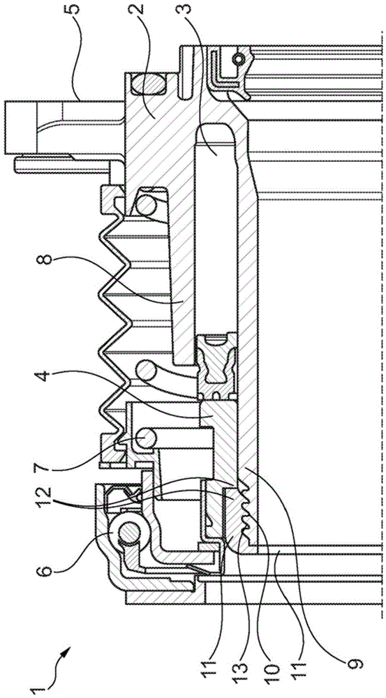
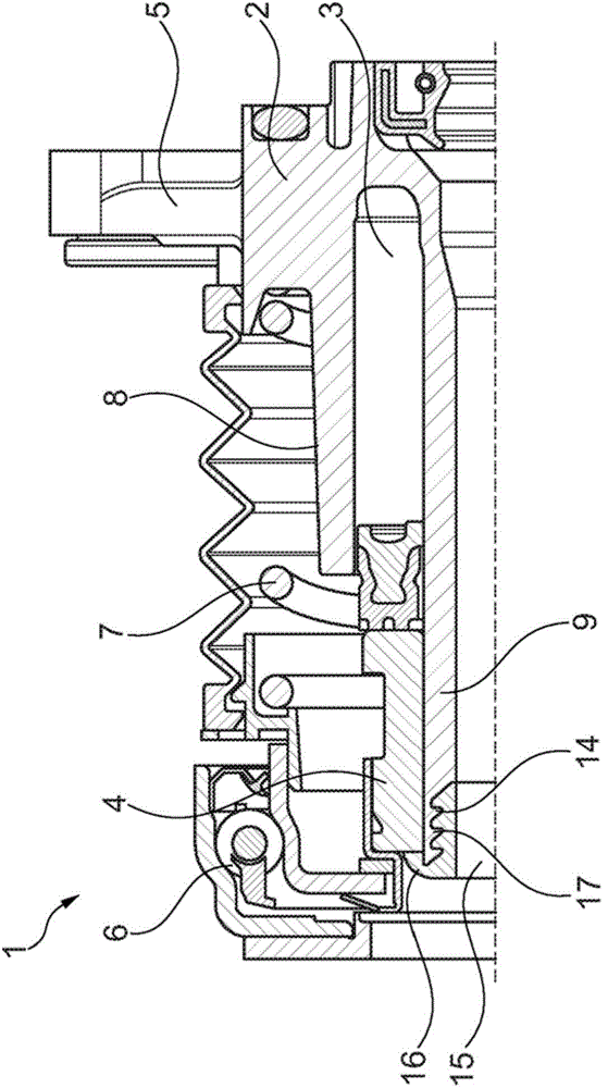
[0020] exist figure 1 A first exemplary embodiment of a slave cylinder 1 is shown in , which is inserted into a dual clutch transmission. The slave cylinder 1 here consists of a cylinder housing 2 made of plastic, which has an annular pressure chamber 3 in which a piston 4 is mounted so that it can move in the axial direction. Via a connecting line, not further shown, of the cylinder housing 2 , hydraulic fluid enters the pressure chamber 3 and actuates the piston 4 and thus the release bearing 6 .

[0021] The preload spring 7 , which is prestressed against the release bearing 6 , is pressed against the cylinder housing 2 in the region of the fastening device 5 of the slave cylinder. To form the pressure chamber 3 , the cylinder housing 2 has an outer wall part 8 and an inner wall part referred to as a guide sleeve 9 . An external thread 10 is formed on the guide sleeve 9 , onto which a stop nut 11 is screwed. The stop nut 11 engages in the recess 12 of the piston 4 when t...


PUM


Abstract

The invention relates to a piston-cylinder arrangement, in particular a slave cylinder for a clutch actuating device, comprising a cylinder housing (2) which is made of a plastic and in which an annular pressure chamber is formed, in which a piston (4) is mounted so as to be axially movable for actuation of a release bearing (6), wherein the inner wall of the pressure chamber forms a guide tube (9). In a piston-cylinder arrangement which withstands the pressures and temperatures occurring in operation of the clutch actuating device, a stop (11,15) is disposed on the guide tube, facing the release bearing, wherein the stop is formed as a screw connection (10.11;14,15).

Description

technical field [0001] The invention relates to a piston-cylinder arrangement, in particular a slave cylinder for a hydraulic clutch actuating device, comprising a cylinder housing made of plastic, in which an annular pressure chamber is formed, the piston in Axially movably mounted in said pressure chamber to operate the release bearing, wherein the inner wall of the pressure chamber forms a guide sleeve. Background technique [0002] A hydraulic clutch actuating device is known, in particular for a center clutch of a dual clutch transmission, in which the cylinder housing is made of plastic. The cylinder wall of the cylinder housing delimits radially outward an annular pressure chamber in which an annular piston operatively connectable to a clutch is accommodated so as to be displaceable. The cylinder housing is here formed by two cylinder wall parts arranged concentrically with one another, wherein the inner cylinder wall part forms the delimitation of the pressure chamb...

Claims


Application Information

Patent Timeline
IPC IPC(8): F16D25/08F16D25/12
CPCF16D25/083F16D25/12F16D23/148F15B15/1466F15B15/24F16J1/01F16J10/02
Inventor 罗兰德·韦尔特塞巴斯蒂安·洪泽尔曼扬·萨克舍夫斯基西蒙·奥特曼
Owner SCHAEFFLER TECH AG & CO KG
Learn More