Eureka AIR delivers breakthrough ideas for toughest innovation challenges, trusted by R&D personnel around the world.

A method for improving the spurious-free dynamic range of microwave photonic links

A technology of microwave photonic link and dynamic range, which is applied in the directions of optical fiber radio, optical fiber transmission, eliminating distortion/dispersion, etc., and can solve problems such as increasing system cost

Active Publication Date: 2019-01-18
BEIJING UNIV OF POSTS & TELECOMM
View PDF1 Cites 0 Cited by
  • Summary
  • Abstract
  • Description
  • Claims
  • Application Information

AI Technical Summary

Problems solved by technology

The first scheme needs to strictly control the three DC bias voltages of the dual-parallel MZM, which is easily affected by the DC drift of the modulator, while the second scheme needs to use complex instruments to control the optical sideband phase, which greatly increases the system the cost of

Method used


Image

  • A method for improving the spurious-free dynamic range of microwave photonic links
  • A method for improving the spurious-free dynamic range of microwave photonic links
  • A method for improving the spurious-free dynamic range of microwave photonic links

Examples


Embodiment Construction

[0016] Embodiments of the present invention will be described in detail below with reference to the accompanying drawings.

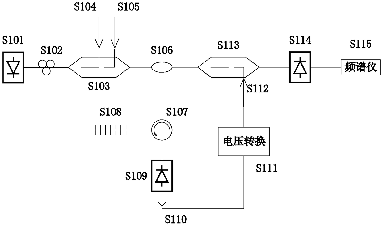
[0017] figure 1 A block diagram of a highly linearizable microwave-photonic link based on automatic gain control is described in . Where S101 is the input laser, which passes through the polarization controller S102 and enters the S103 single-electrode Mach-Zehnder intensity modulator, the microwave signal S104 is loaded to the microwave input port of S103, and the DC bias voltage S105 is loaded to the bias voltage input port of S103, Make the transfer function of S103 at the quadrature bias point. The modulated light enters the S106:50:50 optical beam splitter, which splits the light into two paths. One of them is used as monitoring light, which enters S108 through S107 optical circulator: Bragg grating, the optical sideband with radio frequency frequency is transmitted, the optical carrier is reflected back and injected into S109 photodetector, and t...

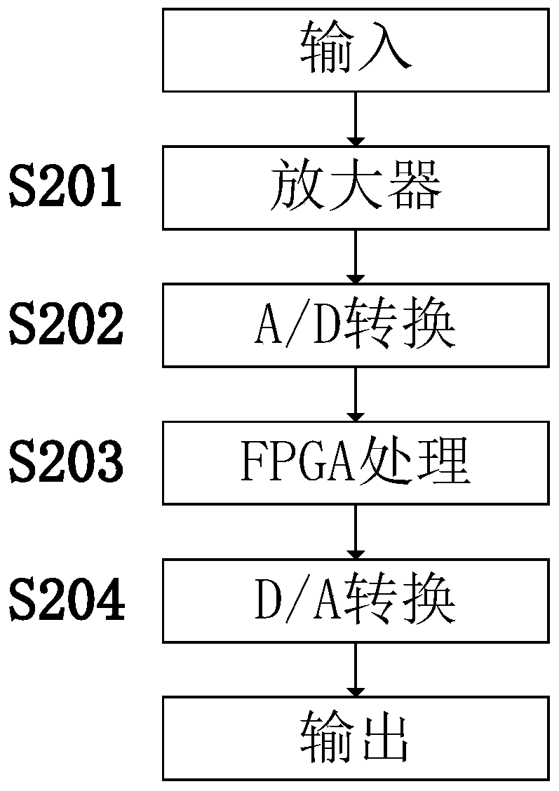

PUM


Abstract

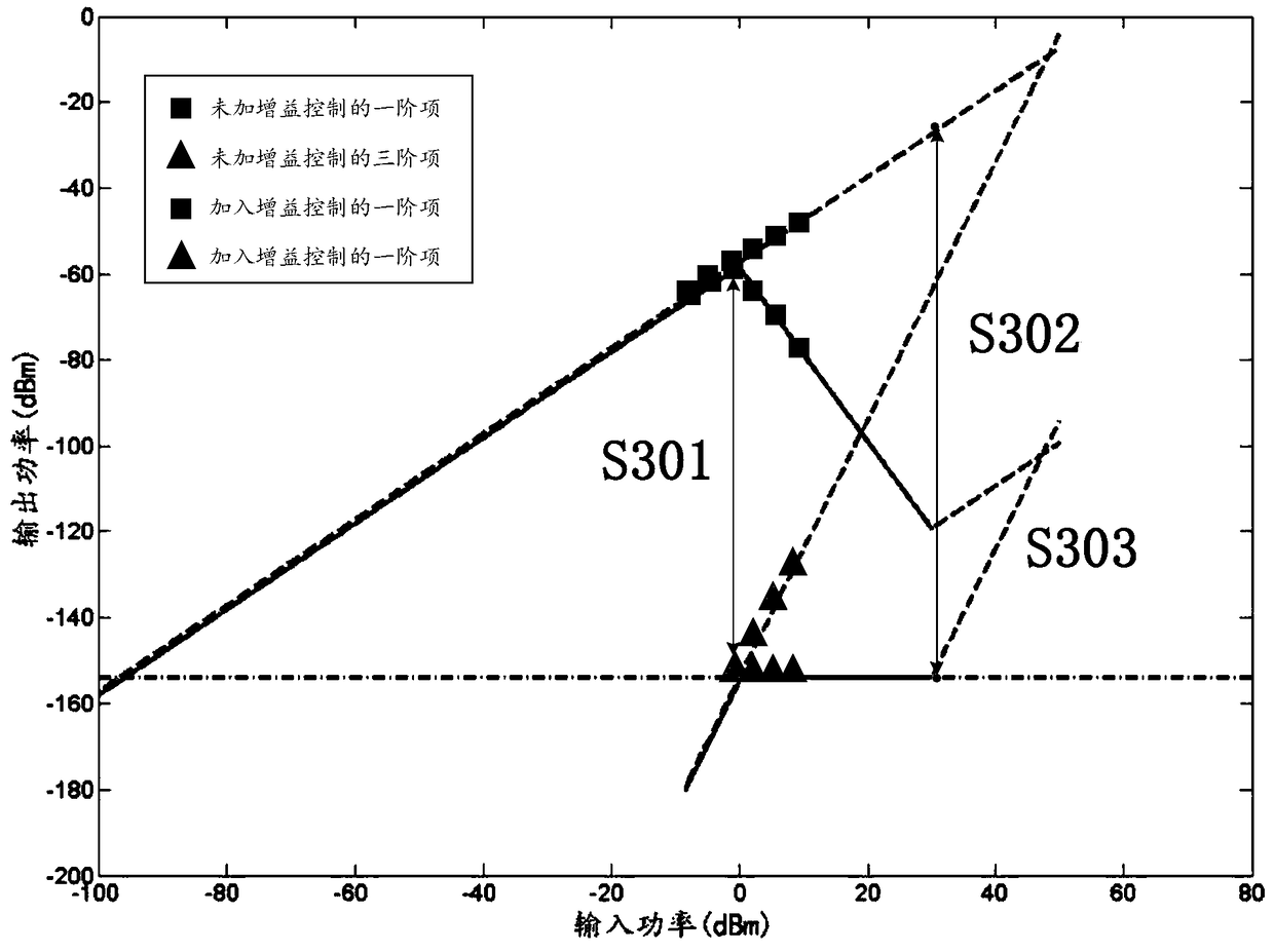
The invention provides a new microwave photonic link SFDR (Spurious Free Dynamic Range) enlarging method. According to the method, an automatic light gain control function is additionally increased in front of a photodetector of a link, light power entering into the photodetector is traced and tuned, so that the total power of third-order cross modulation is less than a noise bottom, furthermore fundamental frequency item power greater than the noise bottom is ensured, and thus, the purpose of enlarging the SFDR is achieved. The automatic gain link is composed of a light beam splitter, a circulator, a fiber bragg grating, the photodetector, a voltage conversion module and a light intensity modulator, wherein the received light is split into two beams by the light beam splitter, one light beam serves as monitoring light, after carrier wave is filtered out by the grating, the monitoring light is subjected to photoelectric conversion, so that a control voltage signal is formed. The control voltage is injected into the direct current bias input port of the light intensity modulator in front of the photodetector, the intensity of the other light beam is controlled by use of the optical interference theory, and the automatic light gain control function is achieved, so that the SFDR of the whole link is enlarged.

Description

technical field [0001] The invention relates to a method for improving the stray-free dynamic range of a microwave photon link, more specifically, it relates to the combined use of electro-optical intensity modulation and optical automatic gain control. Background technique [0002] Microwave photonics is a cross-platform discipline intersecting the microwave field and photonics field. It was formally proposed in 1991. Its essence is to use photonics technology to generate, eliminate, process, and analyze microwave signals. Due to its inherent advantages such as low transmission loss of optical signals, microwave photonics has been researched and applied in many fields, such as broadband wireless access networks, satellite communications, optical signal processing, electronic warfare systems, and optical coherence tomography. In these application fields, while people are pursuing high speed, high bandwidth and large dynamic range of the system, they also have high requiremen...

Claims


Application Information

Patent Timeline
Patent Type & Authority Patents(China)
IPC IPC(8): H04B10/2507H04B10/2575
Inventor 喻松叶辛萌蒋天炜李丹谢志鹏吴锐欢顾畹仪
Owner BEIJING UNIV OF POSTS & TELECOMM
Why Eureka
Eureka Blog
Learn More