
Full automatic electronic deposition system

An electron beam deposition, fully automatic technology, applied in the direction of ion implantation plating, metal material coating process, coating, etc., can solve the problems of high cost, large size of vacuum locking mechanism, long production time, etc., and achieve perfect alarm function And safety interlock device, save the pumping time, improve the output effect

Inactive Publication Date: 2015-05-20
SHENYANG SCI INSTR RES CENT CHINESE ACAD OF SCI
View PDF6 Cites 2 Cited by
  • Summary
  • Abstract
  • Description
  • Claims
  • Application Information

AI Technical Summary

Problems solved by technology

At present, there are two types of thin film preparation equipment used in the field of various thin films on glass, plastic and ceramic substrates. One is single-cavity electron beam deposition equipment. The single production time of equipment with this structure is too long, which leads to high production capacity. Very low, no capacity for continuous production
The other is imported multi-chamber electron beam deposition equipment, which can realize automatic production, but the sample support plate is an overall umbrella structure. Due to the weight problem, the size of the support plate is small, the output per time is low, and the size of the vacuum locking mechanism is large. ,higher cost

Method used


Image

  • Full automatic electronic deposition system
  • Full automatic electronic deposition system

Examples


Embodiment Construction

[0024] The present invention will be described in further detail below in conjunction with the accompanying drawings.

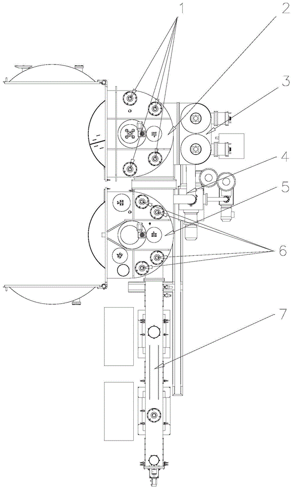
[0025] Such as figure 1 As shown, the present invention includes a process chamber 2, a loading chamber 5, a transmission chamber 7, a vacuum pumping system and a fully automatic transmission mechanism, wherein the process chamber 2, the loading chamber 5 and the transmission chamber 7 are connected sequentially from top to bottom, and the process A vacuum locking device is provided between the chamber 2 and the loading chamber 5 . The process chamber 2 , the loading chamber 5 and the transfer chamber 7 are all connected to the vacuum pumping system, and the automatic transfer mechanism automatically picks and places the sample substrate in the process chamber 2 and the loading chamber 5 . The process chamber 2, the loading chamber 5 and the transfer chamber 7 are respectively communicated with the clean air backfill system.

[0026] Described vacuum pumpin...


PUM


Abstract

The invention belongs to the technical field of plating of various films on glass, plastic and ceramic substrates, and particularly relates to a full automatic electronic beam deposition system. The full automatic electronic beam deposition system comprises a technological cavity, a loading cavity, a transmission cavity, a vacuum pumping system and a full automatic transmission mechanism, wherein the technological cavity, the loading cavity and the transmission cavity are sequentially communicated; the technological cavity, the loading cavity and the transmission cavity are all connected with the vacuum pumping system, and the full automatic transmission mechanism automatically takes sample substrates out of and put in the technological cavity and the loading cavity. The full automatic electronic deposition system has a high yield, reduces the air pumping time of the technological cavity after a sample loading plate is changed each time. The full automatic electronic deposition system simultaneously carries out the technological process of the technological cavity and the process of taking the sample loading plate out of and putting in the loading cavity; and except for a technological cavity door and a loading cavity door arranged inside a clean room, the other parts can be put in common environments, so that the cost is lowered.

Description

technical field [0001] The invention belongs to the technical field of coating various thin films on glass, plastic and ceramic substrates, in particular to a fully automatic electron beam deposition system. Background technique [0002] Through the application of electron beam deposition, the surface of the plastic is metallized, and the combination of organic materials and inorganic materials greatly improves its physical and chemical properties. Make the surface smooth and improve the surface hardness. The original plastic surface is soft and easily damaged. Through vacuum coating, the hardness and wear resistance are effectively increased; to reduce the water absorption rate, the more coating times, the less pinholes, and the lower the water absorption rate. The product is not easy to deform, easy to clean, and does not vacuum. The electron beam deposition method is a continuous automatic production method with the most mature technology and relatively simple operation ...

Claims


Application Information

Patent Timeline
Patent Type & Authority Applications(China)
IPC IPC(8): C23C14/30C23C14/56
Inventor 雷震霖赵崇凌李士军洪克超徐宝利张健张冬王磊李松林峰雪
Owner SHENYANG SCI INSTR RES CENT CHINESE ACAD OF SCI
Learn More