


Quick Research
Generate reliable direction feasibility study reports for your R&D in just a few steps.

Technical Q&A
Discover and master advanced knowledge NOW. Basics, ideas, possibilities, all at once.

Find Solutions
As an expert in R&D theories, this can generate solutions to your technical problems instantly.

Evaluate Feasibility
Analyze your overall solution with one click, know your potential R&D risks in advance.

Monitor Landscape
Get weekly tech updates, stay abreast of the latest tech innovations and key insights.
3d printer wire feeding device
A technology of 3D printer and wire feeding device, applied in 3D object support structure, additive manufacturing, processing and manufacturing, etc., can solve the problems of long manual operation time, low efficiency, inconvenience, etc., to simplify wire feeding operation and improve wire feeding. The effect of efficiency
- Summary
- Abstract
- Description
- Claims
- Application Information
AI Technical Summary
Problems solved by technology
Method used
Image

Examples
Embodiment 1
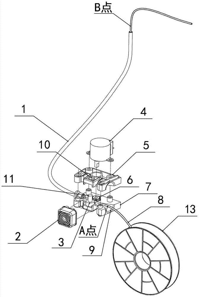
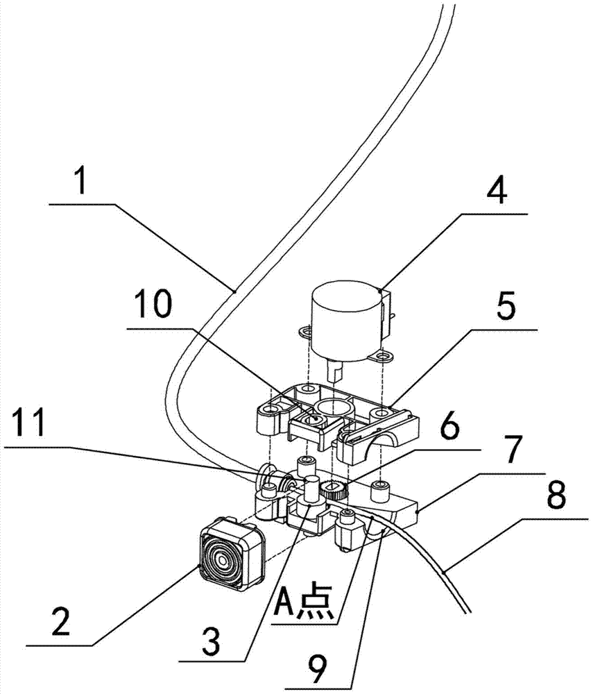
[0022] Embodiment 1: the assembly drawing of embodiment 1 is as figure 1 As shown, the assembly drawing is shown in Figure 4 as shown, figure 1 Partial enlarged picture of figure 2 As shown, it includes a wire guide tube 1, a button 2, a sliding bearing 3, a motor 4, a gear 6, a fixed bracket, and a wire feeding port 9.
[0023] The fixed bracket includes an upper fixed bracket 5 and a lower fixed bracket 7, and the upper fixed bracket 5 and the lower fixed bracket 7 are combined to form a wire feeding cavity.
[0024] The fixed bracket is provided with a slideway that limits the slide bearing 3 to slide back and forth, and a button 2 that can push the slide bearing 3 to slide along the slideway. The sliding bearing 3 is slidably arranged in the wire feeding cavity through the slideway. The gear 6 is rotatably arranged in the wire feeding cavity, and is fixedly connected with the drive output shaft of the motor 4 . The sliding limit direction of the slideway is the dire...
Embodiment 2
[0028] Embodiment 2: structure is basically the same as Embodiment 1, and the similarity is no longer repeated, and the difference is:
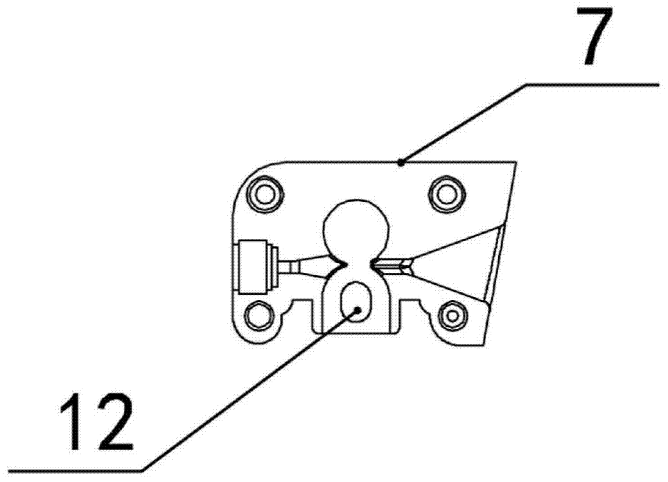
[0029] Specifically in this embodiment 2, the upper slideway 10 is an upper slideway arranged on the inner surface of the upper fixed bracket 5 facing the wire feeding chamber; the slideway 12 is arranged on the lower fixed bracket 7 facing the wire feeding chamber Sliding grooves on the inner surface of the body.
[0030] The upper end of the sliding bearing 3 is located in the upper chute, and the lower end is located in the lower chute, and is arranged in the wire feeding cavity so as to slide back and forth along the sliding direction of the upper and lower chute.
[0031] The groove bottoms of the upper chute and the lower chute are elongated or oval or gourd-shaped.
[0032] Taking Embodiment 1 as an example, the working process of the wire feeding device is as follows: the consumables tray 13 is equipped with tubular or filamentary co...
PUM
 Abstract
Description
Claims
Application Information
 - R&D Engineer
- R&D Manager
- IP Professional
- Industry Leading Data Capabilities
- Powerful AI technology
- Patent DNA Extraction
Browse by: Latest US Patents, China's latest patents, Technical Efficacy Thesaurus, Application Domain, Technology Topic, Popular Technical Reports.
© 2024 PatSnap. All rights reserved.Legal|Privacy policy|Modern Slavery Act Transparency Statement|Sitemap|About US| Contact US: help@patsnap.com