The wiring structure of the wire feeding winch

A wiring structure and wire feeding technology, which is applied in the wiring structure field of the wire feeding winch, can solve the problems of periodic tension changes, large space occupation, and high cost, and achieve the effects of stable wire feeding tension, high wire feeding efficiency, and reasonable structure

Inactive Publication Date: 2015-08-19
ZHEJIANG BAOLONG MACHINERY
View PDF6 Cites 0 Cited by
  • Summary
  • Abstract
  • Description
  • Claims
  • Application Information

AI Technical Summary

Problems solved by technology

The disadvantage of this structure is caused by the unfixed position of the wire head on the winch, resulting in unstable wire feeding and periodic changes in tension. At the same time, the wire feeding mechanism of this structure breaks suddenly when it encounters the wire during wire feeding. , it is impossible to send a signal to the equipment through the wire feeding mechanism itself, so that the manufacturing equipment will not work normally due to lack of materials for a period of time
[0003] At present, there are also some wire feeding winches that can overcome the above problems on the market, but they all have complex structures, high costs, and take up too much space in production, which is inconvenient when batch wire feeding is required.

Method used


Image

  • The wiring structure of the wire feeding winch
  • The wiring structure of the wire feeding winch

Examples


Embodiment 1

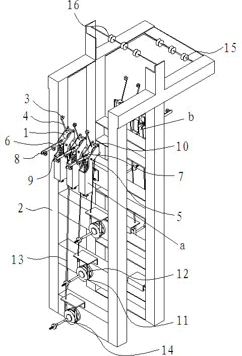
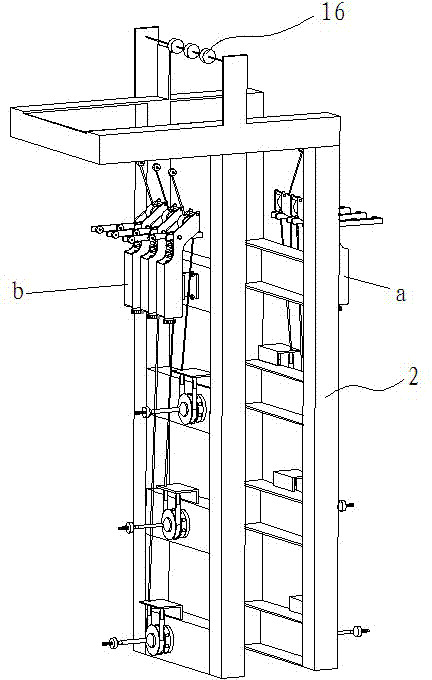
[0022] The wiring structure of the wire feeding winch includes several wire feeding mechanisms, each of which is provided with an output wheel 3; several wire feeding mechanisms form a wire feeding unit, and two groups of the wire feeding units are arranged oppositely to form a feeding wheel. Line unit group, two groups of wire feeding units are respectively forward wire feeding unit a and rear wire feeding unit b, the upper end of the rear wire feeding unit b group is fixed with a wheel frame, and the wheel frame is provided with parallel to each other and the The two sets of transition wheels perpendicular to the wire feeding direction of the wire feeding mechanism are the first transition wheel 15 and the second transition wheel 16 respectively, and the first transition wheel 15 protrudes from the wire feeding end of the back wire feeding unit b On the outside, the second transition wheel 16 protrudes above the wire feeding end of the rear wire feeding unit b.

[0023] The ...


PUM


Abstract

A wire distributing structure of a wire feeding capstan comprises a plurality of wire feeding mechanisms, wherein each wire feeding mechanism is provided with an output wheel; the plurality of wire feeding mechanisms define a wire feeding unit; two groups of wire feeding units are arranged back to back to form a wire feeding unit group; the two groups of wire feeding units consist of a front wire feeding unit and a back wire feeding unit; the upper end of the back wire feeding unit is fixedly provided with a wheel carrier; the wheel carrier is provided with two groups of transition wheels which are parallel to each other and are vertical to the wire feeding direction of the wire feeding mechanisms; the two groups of transition wheels are a first transition wheel and a second transition wheel respectively; the first transition wheel protrudes the outer side of a wire feeding end of the back wire feeding unit; and the second transition wheel protrudes the upper side of the wire feeding end of the back wire feeding unit. The wire distributing structure is reasonable in structure, low in cost, stable in wire feeding tension and high in wire feeding efficiency.

Description

technical field [0001] The invention relates to a wiring structure of a wire feeding winch and belongs to the field of cable manufacturing. Background technique [0002] In the cable manufacturing industry, how to feed wires is the key to product quality and production efficiency, and is also the key to enterprise survival. Commonly used wires are often wound on a winch. At present, the commonly used wire feeding method is to place the winch on a shaft, and maintain the running of the wire through the tension of the cable manufacturing equipment itself, and at the same time apply a certain damping to the winch, so that The wire maintains a certain tension as it enters the device. The disadvantage of this structure is caused by the unfixed position of the wire head on the winch, resulting in unstable wire feeding and periodic changes in tension. At the same time, the wire feeding mechanism of this structure breaks suddenly when it encounters the wire during wire feeding. , ...

Claims


Application Information

Patent Timeline
Patent Type & Authority Patents(China)
IPC IPC(8): B65H59/36B65H59/04
Inventor 王高峰
Owner ZHEJIANG BAOLONG MACHINERY
Why Eureka
Try Eureka