3D printer wire feeding device

A technology of 3D printer and wire feeding device, applied in the direction of additive processing, etc., can solve the problems of long manual operation time, low efficiency, inconvenient, etc., and achieve the effect of simplifying wire feeding operation and improving wire feeding efficiency

Active Publication Date: 2015-05-20
JIANGSU HAOYU ELECTRONICS TECH
View PDF2 Cites 5 Cited by
  • Summary
  • Abstract
  • Description
  • Claims
  • Application Information

AI Technical Summary

Problems solved by technology

[0003] In this way, the manual operation time is longer, and it is very inconvenient and inefficient

Method used


Image

  • 3D printer wire feeding device
  • 3D printer wire feeding device
  • 3D printer wire feeding device

Examples


Embodiment 1

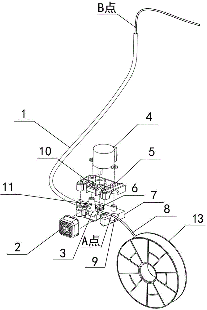
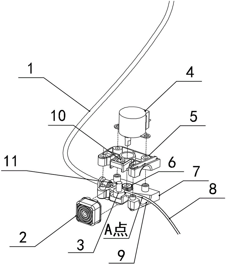
[0022] Example 1: The assembly drawing of Example 1 is as figure 1 As shown, the final assembly drawing is as Figure 4 As shown, figure 1 The partial enlarged view of figure 2 As shown, it includes a guide wire tube 1, a button 2, a sliding bearing 3, a motor 4, a gear 6, a fixed bracket, and a wire feeding port 9.

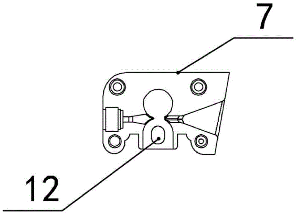
[0023] The fixing bracket includes an upper fixing bracket 5 and a lower fixing bracket 7, and the upper fixing bracket 5 and the lower fixing bracket 7 are combined to form a wire feeding cavity.

[0024] The fixed bracket is provided with a slideway that limits the sliding of the sliding bearing 3 back and forth, and a button 2 that can push the sliding bearing 3 to slide along the slideway. The sliding bearing 3 is slidably arranged in the wire feeding cavity through a slideway. The gear 6 is rotatably arranged in the wire feeding cavity, and is fixedly connected with the drive output shaft of the motor 4. The sliding limiting direction of the slideway is the di...

Embodiment 2

[0028] Example 2: The structure is basically the same as that of Embodiment 1, and the similarities will not be repeated. The difference is:

[0029] Specifically in this embodiment 2, the upper slide 10 is an upper slide groove provided on the inner surface of the upper fixing bracket 5 facing the wire feeding cavity; the lower slide 12 is provided on the lower fixing bracket 7 facing the wire feeding cavity The sliding groove on the inner surface of the body.

[0030] The upper end of the sliding bearing 3 is located in the upper sliding groove, and the lower end is located in the lower sliding groove. The sliding bearing 3 is slidably arranged in the wire feeding cavity along the sliding direction of the upper and lower grooves.

[0031] The groove bottoms of the upper chute and the lower chute are in the shape of a slender strip, an oval or a gourd.

[0032] Taking Example 1 as an example, the working process of the wire feeding device is: the consumable tray 13 is equipped with...


PUM


Abstract

The invention discloses a 3D printer wire feeding device comprising a wire guide pipe, a key-press, a sliding bearing, a motor, a gear, a fixed bracket and a wire feeding opening, wherein a wire feeding cavity is arranged in the fixed bracket, and a slide way for limiting the back-and-forth sliding of the sliding bearing and the key-press which can be used for pushing the sliding bearing to slip along the slide way are arranged on the fixed bracket; the sliding bearing is arranged in the wire feeding cavity in a limited sliding mode by virtue of the slide way; the gear is connected with an output shaft of the motor and is rotatably arranged in the wire feeding cavity; a sliding limiting direction of the slide way is the direction of the sliding bearing close to the gear; and the wire feeding opening is formed in one side of the fixed bracket, the other side of the fixed bracket is connected with the wire guide pipe, and the wire feeding opening is communicated with the middle position between the sliding bearing and the gear to form a wire feeding channel with the wire guide pipe. By adopting the 3D printer wire feeding device disclosed by the invention, wires can be automatically fed to a spray head of a printer, and the wire feeding efficiency can be improved.

Description

technical field [0001] The invention relates to a 3D printer, in particular to a wire feeding device on the 3D printer. Background technique [0002] When the consumables need to be replaced or supplemented in the existing desktop 3D printers, it is necessary to manually install the consumables into the wire guide tube, and then manually push the consumables into the wire guide tube until the consumables are sent to the nozzle of the 3D printer and the nozzle continues. The wire feeding work is completed until the consumables are drawn. [0003] The manual operation time is longer like this, and it is very inconvenient and inefficient. Contents of the invention [0004] Purpose of the invention: In order to overcome the deficiencies in the prior art, the present invention provides a wire feeding device on a 3D printer, which can realize automatic wire feeding to the printer nozzle and improve wire feeding efficiency. [0005] Technical solution: In order to solve the abo...

Claims


Application Information

Patent Timeline
Patent Type & Authority Applications(China)
IPC IPC(8): B29C67/00B33Y30/00
Inventor 魏宏辉魏天浩魏妗羽
Owner JIANGSU HAOYU ELECTRONICS TECH
Why Eureka
Try Eureka