
Sludge disposal device with disposal-assisted structure

A mud discharge device and mud transportation technology, applied in cleaning methods and appliances, cleaning hollow objects, chemical instruments and methods, etc., can solve problems such as increased water injection pressure, difficult discharge, and decreased water absorption capacity of oil layers, and achieve rapid discharge efficiency , prolong the service life, and ensure the effect of using the effect

Inactive Publication Date: 2015-05-20
CHENGDU DAMO PETROLEUM MACHINERY GRP
View PDF8 Cites 0 Cited by
  • Summary
  • Abstract
  • Description
  • Claims
  • Application Information

AI Technical Summary

Problems solved by technology

Deposited at the bottom of the sewage treatment container, it is difficult to discharge, causing the reinjected purified sewage to seriously exceed the standard of suspended solids due to the existence of oily sludge, block the fine filter device, pollute the formation, reduce the water absorption capacity of the oil layer, and the water injection pressure continues to increase
[0003] The existing sludge discharge process cannot effectively discharge the sludge that is silent at the bottom of the large tank. With the accumulation of time, a large amount of sludge will remain in the tank, waiting to be removed after opening the tank, which seriously affects the sewage settlement effect, and also Will increase the workload of maintenance workers

Method used


Image

  • Sludge disposal device with disposal-assisted structure

Examples


Embodiment 1

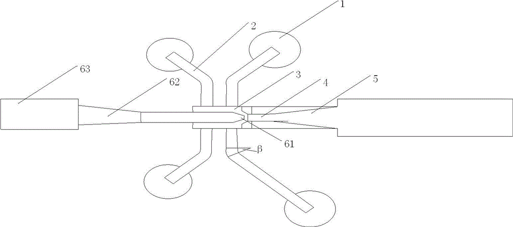
[0024] Such as figure 1 As shown, a mud discharge device with a drainage aid structure includes a mixing pipe 4, a diffusion pipe 5, a mud introduction chamber 3, a suction cup 1, a mud transportation pipe 2, and a drainage aid system, wherein the suction cup 1 and the mud transportation pipe 2 are both 4;

[0025] Each of the suction cups 1 and each of the sludge conveying pipes 2 are correspondingly connected to form a sludge conveying end, and the four sludge conveying ends are all connected through the sludge conveying pipe 2 and the sludge introduction chamber 3 and are evenly distributed in the sludge introduction. On both sides of the chamber 3, the mud transport pipe 2 is an elbow, and the curvature β is 25-35°;

[0026] One end of the mud introduction chamber 3 is connected to the mixing pipe 4, the mixing pipe 4 is connected to the diffuser pipe 5, and the other end of the mud introduction chamber 3 is connected to the drainage aid system, which includes a nozzle 61...

Embodiment 2

[0029] Similar to Example 1, the difference is:

[0030] The mixing tube 4 is a rectangular tube, and the diffuser tube 5 is trumpet-shaped. The design of the mixing tube 4 is conducive to the stable mixing of the dirt here so as not to reduce the removal effect, and the horn-shaped design of the diffusion tube 5 can facilitate the smooth and rapid discharge of the dirt.

[0031] The length ratio between the mixing tube 4 and the diffuser tube 5 is 1:5-8. Experiments show that the length ratio between the mixing tube 4 and the diffuser tube 5 has a certain influence on the discharge effect of the pollutants. Within the range of the length ratio of 1:5-8, the discharge efficiency is fast, and there is basically no deposition dead zone .

[0032] The mixing tube 4 and the diffuser tube 5 are connected by an arc. This smooth arc design is also convenient for the smooth discharge of dirt.

[0033] The diffuser 5 includes a trumpet-shaped front end and a cylindrical rear end, w...


PUM


Abstract

The invention discloses a sludge disposal device with a disposal-assisted structure. The device comprises a mixing pipe, a diffusing pipe, a sludge extracting chamber, sucking discs, sludge delivery pipes and a disposal-assisted system, wherein the number of the sucking discs is four and the number of the sludge delivery pipes is four; each sucking disc is connected with the corresponding sludge delivery pipe and form a sludge delivery end, four sludge conveying ends are all connected with the sludge extracting chamber through the sludge delivery pipes and are all distributed on two sides of the sludge extracting chamber, the sludge delivery pipes are bending pipes, and the bending degree beta is 25-35 degrees. The sludge disposal device with the disposal-assisted structure can effectively remove the sludge deposited on the bottom of a container through arranging the disposal-assisted system, and the sludge disposal device is simple in structure; the sludge removing efficiency is high and effective, and the workload of opening a can by a maintenance worker can be relieved.

Description

technical field [0001] The invention relates to the field of petroleum machinery, in particular to a mud discharge device with a drainage aid structure. Background technique [0002] In the process of extracting crude oil, the tiny particles in the reservoir enter the surface treatment system together with the production fluid, which is the main source of sludge in the oil production sewage. In addition, the flocs formed by adding water purifiers in the sewage purification treatment, Equipment and pipeline corrosion products, scale, bacteria (corpse), etc. The oily sludge composed of these substances generally has the characteristics of high oil content, high viscosity, fine particles, and poor fluidity. Deposition at the bottom of the sewage treatment container is not easy to discharge, causing the reinjected purified sewage to seriously exceed the standard of suspended solids due to the existence of oily sludge, block the fine filter device, pollute the formation, reduce t...

Claims


Application Information

Patent Timeline
IPC IPC(8): B08B9/08
CPCB08B9/08B08B2209/08
Inventor 贺昶明
Owner CHENGDU DAMO PETROLEUM MACHINERY GRP
Learn More