A lightweight crack-resistant track structure

A track and light-weight technology, applied in the engineering field, can solve problems such as affecting the restraint stiffness of connecting rods, increasing the dead weight of the upper part of the bridge, and adversely affecting the overall prefabrication of the factory. Effect

Active Publication Date: 2017-01-04
SHENZHEN MUNICIPAL DESIGN & RES INST
View PDF5 Cites 0 Cited by
  • Summary
  • Abstract
  • Description
  • Claims
  • Application Information

AI Technical Summary

Problems solved by technology

[0003] The integrity of the slab track is relatively good, but its existing problems are: the amount of concrete used is large, the cost of the project is high, and its own weight is relatively large, especially when it is used on a bridge, the weight of the upper part of the bridge is increased; in order to ensure the safety of the bridge , the cross-sectional dimensions of other components on the bridge will also increase accordingly, which will increase the cost of the bridge itself
[0004] The trapezoidal track structure has the advantages of light weight, and it is convenient to arrange damping elements under the trapezoidal track. The problem is that the connecting parts at both ends of the trapezoidal track connecting rods are prone to cracking during the use of the trapezoidal track structure.
When the plastic hinge stiffness degrades seriously, it will affect the restraining stiffness of the connecting rod to the track beam laterally, endangering the driving safety of the train
[0005] The problems of the sleeper track structure are: the structure is relatively scattered, which is not conducive to the overall prefabrication of the factory, and is not conducive to the arrangement of vibration-damping components

Method used


Image

  • A lightweight crack-resistant track structure
  • A lightweight crack-resistant track structure
  • A lightweight crack-resistant track structure

Examples


Embodiment Construction

[0021] The following will clearly and completely describe the technical solutions in the embodiments of the present invention with reference to the accompanying drawings in the embodiments of the present invention. Obviously, the described embodiments are only some, not all, embodiments of the present invention. Based on the embodiments of the present invention, all other embodiments obtained by persons of ordinary skill in the art without creative efforts fall within the protection scope of the present invention.

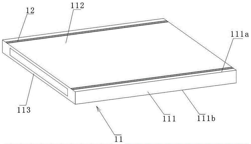
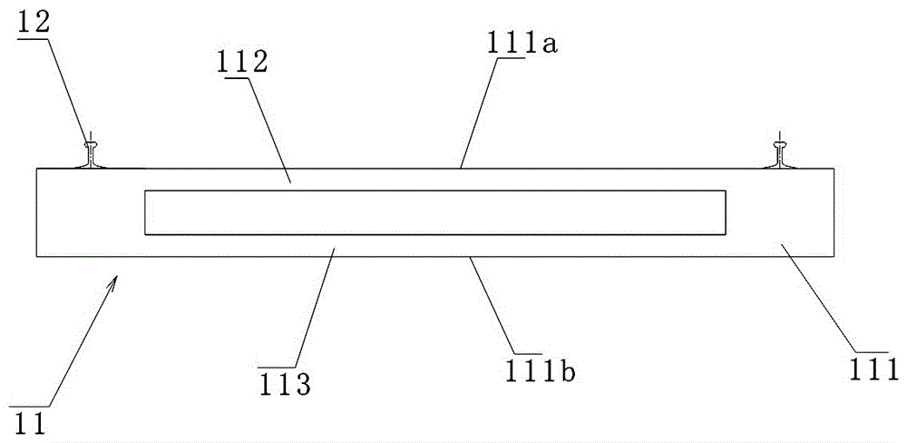
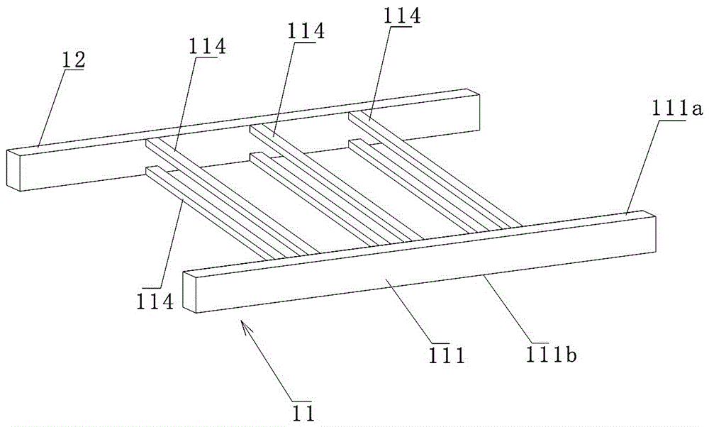
[0022] see in conjunction Figure 1-Figure 2 , is an embodiment of the box-type track beam structure of the light crack-resistant track beam of the present invention.

[0023] Such as figure 1 As shown, the box-shaped track beam structure in this embodiment, compared with the previous trapezoidal track structure, the track structure has increased the transverse connection stiffness and transverse section moment of inertia of the track beam, including: track beam 1...


PUM


Abstract

The invention discloses a light anti-crack track structure. The light anti-crack track structure comprises a track beam, tracks and connecting plates or connecting rods. The track beam comprises two track beam bodies, and the extension direction of the two track beam bodies is the same as the extension direction of the two tracks; the connecting plates or the connecting rods are arranged between the track beam bodies, the connecting plates comprise the top plate and the bottom plate, and the top plate and the bottom plate are arranged between the track beam bodies and kept flush with the top surfaces and the bottom surfaces of the track beam bodies respectively; the top plate, the bottom plate and the track beam bodies form a box structure of which the section is rectangular; the multiple rows of connecting rods are double-layer connecting rods which are kept flush with the top surfaces and the bottom surfaces of the track beam bodies respectively and are the same in section shape, and the plane where any row of double-layer connecting rods are located is perpendicular to the side faces of the track beam bodies. According to the light anti-crack track structure, the transverse connecting rigidity and section anti-bending inertia moment of the track beam can be increased, and the section anti-bending performance of the track beam can be improved; flexible arrangement of damping elements is facilitated, and the construction cost is easier to control.

Description

technical field [0001] The invention relates to the field of engineering, in particular to a light-weight anti-crack track structure. Background technique [0002] With the continuous expansion of the scale of cities in our country, the demand for the development of public transportation has become increasingly strong. A large number of new transportation lines have appeared on the city map. As the most effective way to relieve urban traffic pressure, urban rail transit has been recognized in recent years. rapid development. At present, the structural forms of rail transit mainly include slab track structure, trapezoidal track structure, and sleeper track structure. [0003] The integrity of the slab track is relatively good, but its existing problems are: the amount of concrete used is large, the cost of the project is high, and its own weight is relatively large, especially when it is used on a bridge, the weight of the upper part of the bridge is increased; in order to e...

Claims


Application Information

Patent Timeline
Patent Type & Authority Patents(China)
IPC IPC(8): E01B1/00E01B2/00E01D19/00
CPCE01B1/00E01B2/00E01D19/00
Inventor 陈宜言于芳姜瑞娟
Owner SHENZHEN MUNICIPAL DESIGN & RES INST
Why Eureka
Try Eureka