
Ultra-high speed aircraft thermal protection and drag reduction method and system

An aircraft, ultra-high-speed technology, applied in the thermal protection device of the aerospace vehicle, the device for the control of the living conditions of the aerospace vehicle, and the influence of the air flow flowing through the surface of the aircraft, etc., can solve the problem of heat protection, accidental failure, and endanger Carry system security and other issues to achieve the effect of improving energy efficiency and limit speed, slowing down or avoiding thermal barrier phenomenon, and good application prospects

Active Publication Date: 2015-05-13
NINGBO INST OF MATERIALS TECH & ENG CHINESE ACADEMY OF SCI +1
View PDF6 Cites 33 Cited by
  • Summary
  • Abstract
  • Description
  • Claims
  • Application Information

AI Technical Summary

Problems solved by technology

There are two main problems in the flight process of ultra-high-speed aircraft: (1) when the ultra-high-speed aircraft enters and exits the atmosphere, it faces the problem of air stickiness, which requires a lot of energy to overcome the aerodynamic resistance; The aerodynamic shock wave friction heat generation phenomenon, thermal barriers appear, in severe cases, can generate thousands of degrees of high-temperature plasma, resulting in communication interruption, this stage is a high-risk period for aircraft
However, these two methods are difficult to provide thermal protection for a long time, resulting in expensive aircraft needing frequent overhauls or facing the status quo of being eliminated after being used several times
Secondly, it is difficult to control the internal temperature of the aircraft by using these two methods, but the continuous increase of the internal temperature of the aircraft will seriously endanger the safety of the carrying system
In addition, the structure of the relevant protection system is complex and prone to unexpected failures

Method used


Image

  • Ultra-high speed aircraft thermal protection and drag reduction method and system
  • Ultra-high speed aircraft thermal protection and drag reduction method and system
  • Ultra-high speed aircraft thermal protection and drag reduction method and system

Examples


Embodiment 1

[0046] In order to make the technical solution of the present invention clearer, the thermal protection and drag reduction system of the ultra-high-speed aircraft of the present invention will be further described in detail in conjunction with the accompanying drawings. It should be understood that the specific embodiments described here are only used to explain the present invention and not to limit the present invention.

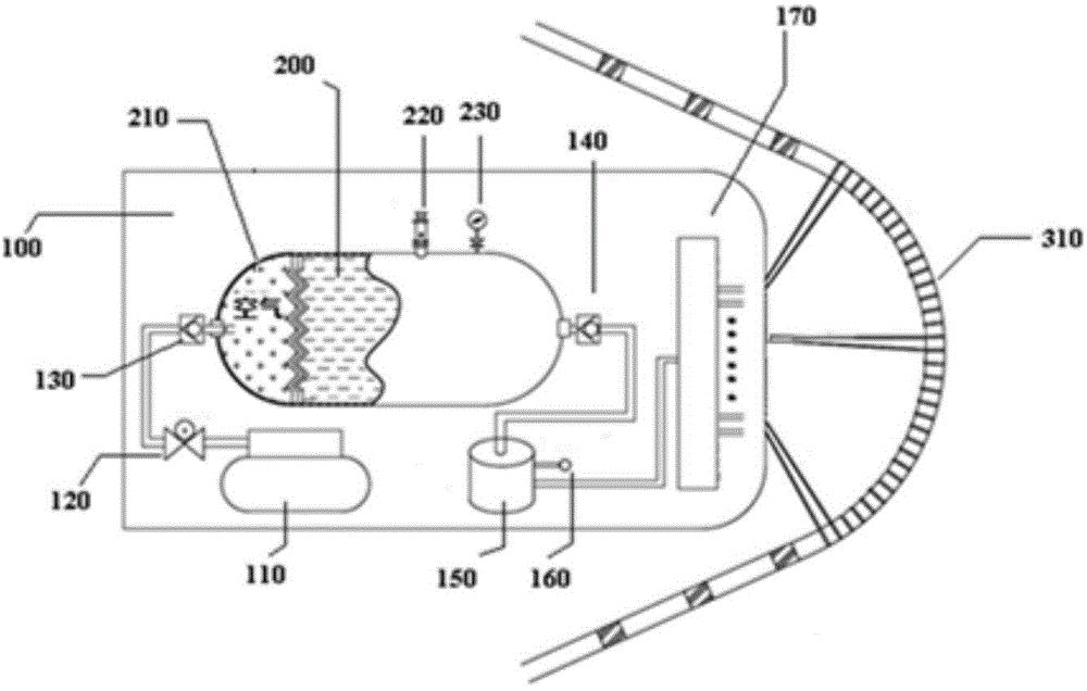
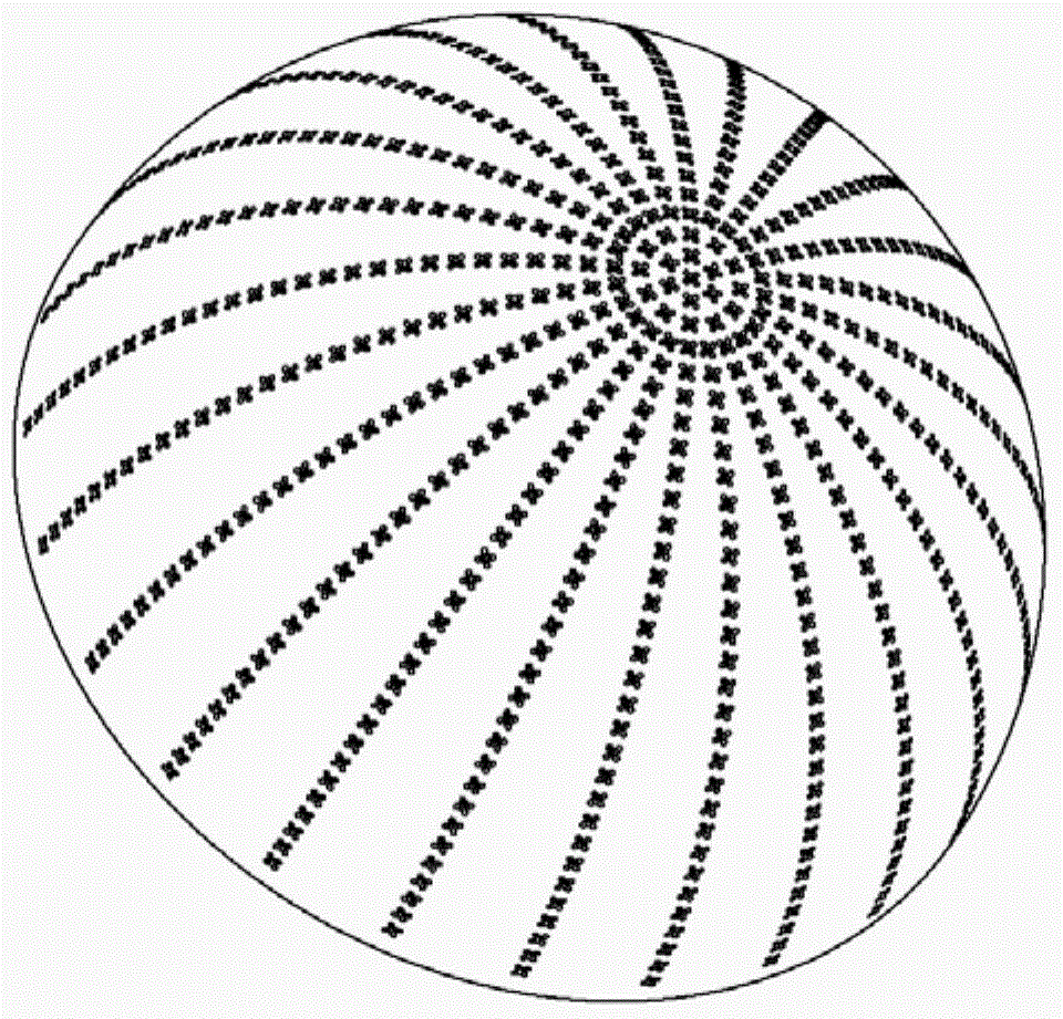
[0047] In this example, if figure 1 As shown, the ultra-high-speed aircraft includes a sealed cavity, and the drag reduction and thermal protection system of the ultra-high-speed aircraft includes a cold source 200 arranged inside the sealed cavity of the ultra-high-speed aircraft, and is used to convert the cold source 200 into a high-pressure gas and eject it The cold source driving device 100. The wall surface 310 of the head portion of the sealed cavity of the ultra-high-speed aircraft is a sandwich structure. figure 2 is a schematic diagram of the ...


PUM


Abstract

The invention provides an ultra-high speed aircraft thermal protection and drag reduction method and system. The method includes that a cold source is arranged inside the cavity of an ultra-high speed aircraft, a plurality of micropores are arranged in the wall surface of the cavity, and the cold source is ejected out of the micropores in a high-pressure air state under the action of driving force to form an air film on the outer surface of the cavity. The air film can perform thermal protection on the ultra-high speed aircraft, viscous drag of the aircraft with external air can be effectively reduced, thermal barrier is favorably alleviated or eliminated, security of the ultra-high speed aircraft is improved, service life is prolonged, and a good application prospect is achieved. A cold source driving unit comprising an air pump, a cold source storer and a buffer is adopted in the system, the air pump supplies compressed air to the cold source storer during the operation state, the cold source enters the buffer to be vaporized under the action of air pressure, and the air is ejected from the micropores to form the air film under the action of pressure.

Description

technical field [0001] The invention belongs to the technical field of ultra-high-speed aircraft, in particular to a method and system for thermal protection and drag reduction of ultra-high-speed aircraft. Background technique [0002] Ultra-high-speed aircraft refers to aircraft with a flight speed above Mach 5, including rockets, missiles, spacecraft, space shuttles, aerospace aircraft, etc. There are two main problems in the flight process of ultra-high-speed aircraft: (1) when the ultra-high-speed aircraft enters and exits the atmosphere, it faces the problem of air stickiness, which requires a lot of energy to overcome the aerodynamic resistance; The aerodynamic shock wave friction heat generation phenomenon, thermal barrier, in severe cases, can generate thousands of degrees of high-temperature plasma, resulting in communication interruption, this stage is a high-risk period for aircraft. [0003] Regarding air viscosity resistance, current ultra-high-speed aircraft ...

Claims


Application Information

Patent Timeline
IPC IPC(8): B64G1/58F42B10/38
CPCB64C1/38B64D13/006B64G1/50F42B15/34F42B10/38F42B10/40F42B10/46B64G1/58Y02T50/50Y02T50/10B64C2230/16F15D1/008
Inventor 张文武向树红郭春海童靖宇张天润杨旸宋涛
Owner NINGBO INST OF MATERIALS TECH & ENG CHINESE ACADEMY OF SCI
Learn More